


Cooling towers (CT) are widely used for variety of heat rejection applications like HVAC industry. A comprehensive design methodology is not available. Hence, design of a small water cooling tower is described in this article.
Cooling tower is generally designed for the average hourly wet bulb temperature (WBT) during summer at the place, where it is going to be used. Induced draught counter flow CT with splash fill is chosen after considering the relevant merits of various types. The CT characteristic and height are computed from empirical relationships. The fill structure is chosen from the commonly used fill configuration. The detailed design of CT system is described below.
i. Selection of WBT & DBT: For example, the average of hourly wet bulb temperature in a site during summer (April to July) is 20.3 deg celciusand dry bulb temperature is 25.4 °C.
ii. Selection of type of tower: The natural draught cooling towers (ND CT) tend to be quite large, built in hyperbolic contour and initial investment is very high. It is difficult to have strict control on the temperature of cold water out from the CT and the approach to WBT will be high. The operation and maintenance cost is relatively less. Hence, only for very large installations, ND CT is preferred. On the other hand, mechanical draught cooling towers (MD CT) can be of very small capacity, less expensive, larger cooling range and close approach to WBT can be obtained. Forced MD CT causes more recirculation of hot humid air exit from CT as suction to the blower. Cross flow MD CT is thermally less efficient, has more recirculation, needs more maintenance and needs more tower volume for a particular capacity of cooling. Considering all the above factors, induced draught counter flow MD CT is selected.
iii. Design parameters: The cooling tower is proposed to be designed with the following data:
- Design WBT is 20.3 °C
- Design DBT is 25.4 °C
- Atmospheric pressure is 92.0 kPa
- Water temperature inlet to CT is 35 °C
- Water temperature out from CT is 30 °C
- Water flow rate, m is 1,200 kg/h or l/hiv. L/G ratio: The MD CTs are generally designed with water to air flow (L/G) ratio of 0.75 to 1.5. L/G ratio of 1.2 is chosen for the CT.v. Computation of tower characteristic: From psychrometric chart, enthalpy of inlet air, hi = 62.42 kJ/kg
Enthalpy of outlet air, ![]()
ho = 62.42 + 1.2 x 4.186 x (35-30) = 87.54 kJ/kg


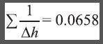
Tower characteristic

vi. Cooling tower capacity: The capacity of the cooling tower is calculated as given below.
Tower characteristic
CT capacity = m Cw DT

(Because, 1 TR = 3.52 kW)
vii. Cross section of the tower: From the nomograph, given in Perry’s hand book, for the above design parameters, the tower area is computed as given below.
- Water concentration of the CT is 4,898 l/h m2.
- The water flow to the CT is 1,200 l/h.

- From this, the area of the CT is calculated as 0.245 m2.
- Hence, CT with cross section of 0.5 m x 0.5 m is chosen.
viii. Fill type: The water to be cooled in a CT is sprayed over the fill which provides large area of contact between water and air stream. The extent of heat transfer that can occur depends on the surface area of the fill. In induced draught CT, the air is induced along the fills through the fan. Two basic types of fills are utilised in modern CTs: Splash type and film type. The factors influencing the choice of fill are its heat transfer performance, maintenance, pressure drop, cost and durability. The film type fill gets chocked very fast, causes more pressure drop and needs more maintenance, although the thermal performance of film type is superior. Splash type fill does not get chocked because of the gap in between the bars, causes less pressure drop and needs less maintenance. Hence, splash type fill is chosen. The commonly used fill geometries are shown in Figure 1. Triangular splash bar (geometry a) is chosen for the project. Since this is a small CT, half the dimension of the common geometry is chosen.
ix. Height of the tower: The height of the tower is calculated directly using the volume transfer coefficient (Ka/L) represented in equation form as given below.
![]()
For the type of fill chosen, l = 0.295, n=0.5

From equation, ![]()
Tower volume, 
Hence, tower height = 1.2 m
x. Fill structure: The overall dimension of the fill matrix is chosen just smaller than the tower dimension so that it can be kept inside the tower. Hence, the fill matrix dimension is 0.49 x 0.49 x 1.2 m height.
xi. Cold water sump: The function of the sump is to collect the water from the fill without spillage. Hence, the area of sump has to be larger than the fill area. The area of the fill is 0.5 m x 0.5 m and the area of the sump is chosen as 0.6 m x 0.6 m. Minimum quantity of water is to be stored in the sump to attain the steady temperature fast during the operation of the cooling tower. Hence, the sump height is chosen as 0.25 m, whereby upto 90 litres of water can be held in the sump for circulation.
xii. Design of water distribution system: The function of the distribution system is to spray the hot water from the geysers evenly over the fill matrix. To ensure the evenly spray of hot water over the fill, it is proposed to have five small pipes at equidistant on either side of the main distribution pipe. In each small pipe, five small holes are put at equidistant, below which a conical plate is fixed to splash the water from each hole. The detailed design procedure is described below.
The design water flow rate to the tower is 1,200 l / h (=1.2 m3/h).
The optimum water velocity inside a cooling water discharge line is 1-3 m/s. Hence, a 19 mm pipe is chosen for both suction & discharge side.
Water velocity ![]()
Velocity, 
Kinematic viscosity, n of water at 32.5 deg celcius(average of cold & hot water) = 0.788 e-6 m2/s
Reynolds number, ![]()
For Re 4,000 to 106, coefficient of friction, ![]()
Loss of head in pipe due to friction, 
a) Suction side head: The pump will be mounted by the side of the cold water sump, so that the suction pipe is at the bottom of the sump. Suction pipe diameter is 19 mm. Pump suction will have a non-return valve (NRV) and no foot valve.
i. Entrance loss =
ii. Loss across NRV 

where z is Coefficient of resistance across 19 mm NRV = 1.9

iii. Pump suction pipe length = 0.3 m
Loss of head in suction pipe due to friction, 
iv. Water level above centre of suction pipe in sump = 0.2 m
v. Net positive suction head = 0.2-(0.035+0.135+0.027)
= 0.003 m
b) Discharge side head: The fill height is 1.2 m. Additional 0.4 m is taken up to main header. The discharge line (length is 1.6 m) will supply water to the heat source.
i. Static head of the system = 1.6 m
ii. Loss of head in discharge pipe due to friction, 
iii. Head loss in heat source = 3.5 m (typical value)
iv. Discharge head = 1.6+0.146+3.5 = 5.319 m
c) Distribution system: The size of main distribution header is 19 mm. To ensure evenly spray of hot water over the fill, it is proposed to have five small pipes at equidistant on either side of the main distribution pipe. In each small pipe, five small holes are put at equidistant. Since the piping is small and short length, it is taken that water flow is equal through each small pipe and also through each small hole.
Water flow in each small pipe ![]()
It is taken that the same water velocity (1.18 m/s, as that of main pipe) is maintained in each small pipe. Hence, diameter of small pipe 
It is taken that the velocity of water through each hole is 2.0 m/s so that water is splashed adequately. Water flow through each hole ![]()
Diameter of each hole 
i. Length of main distribution line = 0.6 m
Head loss in main line due to friction, 
ii. Length of small side pipe = 0.24 m
Reynolds number, Re ![]()

Head loss in small side pipe, 
iii. Loss of head at exit through the 2 mm hole 
Total head of distribution system (THDS) = 0.055+0.092+0.204 = 0.351 m
Total pumping head required = (5.319+0.351)-0.003 = 5.667m
xiii. Pump rating: Pump rated for 5.7 m total head and 1.2 m3/h is required.
Power required by the motor and pump ![]()
h- Efficiency of motor + pump (Considering low capacity, it is taken as 25 per cent)
Power 
A commercially available motor + pump rated with following specification are selected.
Suction & discharge line internal size: 19 mm, Speed = 2700 rpm, 230 V, AC, single phase, 50 Hz, 92 watts, 600-1600 lph & 3-15 m head.
On the discharge line of the pump, a re-circulation pipe with valve will be mounted for flow control, if any, needed.
xiv. Drift eliminator: Drift eliminator basically refers to the baffles placed at outlet of fills to restore the water particles carried, if any, along with the moist air. The drift eliminator should provide minimum resistance to air flow and minimum drift loss. The drift eliminator is proposed to be made with sheet of 490 mm long and 50 mm width (90° bend at 25 mm to form ‘V’ shape). No. of such units are to be arranged with a spacer in between to form the matrix and to be mounted just above the fill matrix.
xv. Induced draught fan: The L/G ratio of the tower is 1.2 and hence, the air flow through the tower is ![]() . A fan rated for 1500 m3/h (with suction side damper for flow control), 1.5 kW is selected for the purpose. The schematic diagram of a small cooling tower is shown in Figure 2.
. A fan rated for 1500 m3/h (with suction side damper for flow control), 1.5 kW is selected for the purpose. The schematic diagram of a small cooling tower is shown in Figure 2.

Conclusion
A simple methodology is described for designing of small cooling tower.


