


In many contracts, the HVAC&R scope of work includes the electrical work related to HVAC&R system as a part of its contracts. Electrical power supply is generally arranged at a single point, terminated in an isolator or circuit breaker by electrical contractors as a part of their scope of works. All further works from this point to various equipment or components are to be arranged or provided by HVAC contractor.
It is quite possible that specialist electrical engineers are not their full time and regular employees and in those instances this part of electrical works is sub-contracted to an electrical sub-contractor. An effort has been made in this article to understand design considerations and precautions from electrical engineer’s point-of-view.
Electrical energy happens to be one of the most versatile forms of energy. Transmission or conveying this energy is easy and converting this energy to rotational or heat or other forms required for specific application is performed by respective appliances.
Being a form of energy, it has an effect on a human body, and results in flow of current through human body if the human body comes in contact with live parts or wires of electrical installation. The human body has a definite resistance to this passage of current (which is dependent on the weight and composition of the individual) and the current is based on the potential or voltage difference between the live parts contacted. This aspect makes it necessary to have a safe to operate electrical system design and installation.

Parameters commonly referred in electrical energy transmission, distribution and consumption are voltage, current, power factor, energy, harmonics etc.
In most of the HVAC&R systems, the power supply is arranged as 415 volts three phase or 230 volts 50 Hz (cycles/sec) frequency, and alternating current (AC).
In few large systems, the chiller packages in particular may be selected to operate at higher voltages like 3.3 or 6.6 kV.
The power supply is arranged in a three phase, five wire system, which includes neutral and protective earth conductors apart from the three lines or phases. This arrangement allows taking a single-phase power supply between any of the lines and neutral, when required.


Design Considerations
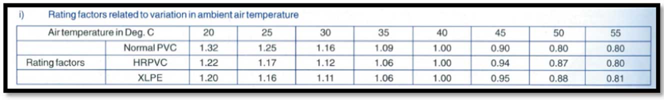
The electrical power has to be distributed to various equipment, appliances, controls etc at the specified location, at appropriate voltage, and has to carry the design current. It is important to remember that every electrical component performance is dependent on the surrounding ambient temperature and de-rating factors have to be applied for actual anticipated ambient temperature conditions.

The installation has to be designed to ensure a safe operation and provide protection against abnormal operating conditions. It is necessary to protect the equipment or apparatus as well as the cables.
Circuit Breakers: One of the most important protection is protecting the installation against short circuit. In most installations, circuit breakers provide this protection. The circuit breakers have a time – current characteristics, which allows continuous operation when the current is normal, allows operation for short duration under overload condition but trips the circuit or isolates the equipment power supply instantly under abnormal high current conditions.
It is a common practice to express the current on unitary basis, and generally these performance curves are on logarithmic scale.

Other protections include single phasing or loss of phase protection, under-voltage protection, over load protection, high temperature of winding, earth fault protection etc.
For the purpose of protection, monitoring current, voltage and other relevant parameters becomes necessary.
Cables: Sizing of cables has to be done carefully as they will be getting heated continuously when energised or carrying currents.
Voltage drop has to be within limits – specified by local electricity authorities – and in some cases like cooling tower or pumps at roof or terrace cable size is dictated by voltage drop rather than the load current.
Some of the cable manufacturers provide data on voltage drop in millivolts per meter length per ampere current flowing and using this data, the anticipated voltage drop for a particular feeder can be calculated. If the voltage drop exceeds the acceptable or specified limit, the calculation has to be repeated using the next higher size cable.
The cables have to be applied with a suitable de-rating factor, depending on the surrounding ambient temperature, spacing between cables, grouping etc.

In many cases, cables are accommodated on cable trays which are bundled together, and the derating of the cables is not considered while selecting cable size.
The derating of cable will be associated with over-heating of cables, leading to failure of insulation followed by short circuiting and eventually fire condition.
Starters: The starting current for drive motor is much higher compared to its full load or operating current and the starting in-rush current requires to be regulated.
Many electricity boards and design consultants specify highest starting current acceptable, and the starters for drive motors have to be selected considering these specified limits.
In some cases, the compressors have a facility to start in un-loaded condition, but the motor still has higher starting current required.


Different types of starters are available – direct-on-line (DOL), start-delta, soft starter etc.
In main equipment like chiller package, the starters required for compressors, condenser fan motors etc are generally incorporated as a part of unit mounted unit panel.
However, the starting current limits specified in the contract documents and specifications have to be communicated to the equipment supplier.
Starters is generally a combination of main power contractors, over-load protection, under voltage protection as a minimum, and allows the control wiring to facilitate sequential operation.
Electrical distribution boards or panels – accommodate the incomer circuit breaker with metering like voltmeter, ammeter, PF meter, energy meter, bus bars and outgoing feeders with metering as specified. These power distributions are assemblies of various switchgear fitted within sheet metal cabinets or enclosures.

Various forms or configurations are available, and design consultants specify the type to be provided.

Motor Control Center (MCC): It is similar to the distribution panels, and will also incorporate the starters for drive motors as well as interlocking for sequential operation of various motors.
It is a standard or common practice to provide the feeders for the packaged chillers, starters for various pumps namely condenser water pumps, chilled water primary pumps and cooling tower fan motor in the main HVAC MCC, which is installed within the main plant room.
In some installations, individual equipment like air handling unit is controlled with a dedicated AHU control panel, located within the respective AHU room. This control panel will accommodate the incomer, duty selection switch, starter or VFD as well as control transformer and control wiring.
When the secondary chilled water pumps are located in separate plant rooms, panels will be provided to cater to these pumps, including the standby pump as applicable. This panel is fed from the main MCC. Sizing of the feeder is based on actual working pumps, and the pump control has to be with a duty selector switch to ensure that the stand-by pump would not start or operate any time.
Cabling and wiring: The cables or wires are used for interconnecting the electrical panels and equipment or controls or drive motors or actuators as well as earthing.
Space required for terminations of large cables and transition from field-cabling to main equipment – aluminium conductor field cables to copper studs on imported equipment has to be identified and allowed in space planning.


IP Rating
Requirement of power supply: In HVAC&R installations, power supply is necessary for various equipment, controls, actuators and the like.
Single line diagrams (SLD) is similar to scheme drawings in HVAC and help understand the overall arrangement.
Some equipment requires three phase power supply while few equipment is suitable for operation on single phase power supply. Generally, control system components are selected to operate on low voltage power like 24 volts to minimise risk of shock to the technicians working on the circuitry.
It is advisable to prepare a full matrix for power supply requirement with comprehensive list of equipment, location, power required in kilowatts, whether three phase or single phase, controls operating voltages, identifying stand-by equipment if any, equipment which needs to be fed from back-up or generator or UPS being emergency support system.
A close co-ordination is necessary between HVACR contractor and electrical works to ensure correctness of design and safe reliable operating system.

Govind Mahadeo Lele,
Associate, C V Raman College of
Engineering, Bhubaneshwar


Модные заметки по выбору модных видов на любой день.
Заметки профессионалов, события, все показы и мероприятия.
https://rftimes.ru/news/2024-09-05-sem-aktualnyh-lukov-2024-ot-brunello-cucinelli