

Over the years, all parts of a commercial refrigerator, such as the compressor, heat exchangers, refrigerant, and packaging, have been improved considerably due to the extensive research and development efforts carried out by academia and industry. However, the achieved and anticipated improvements in conventional refrigeration technology are incremental since this technology is already nearing its fundamentals limit of energy efficiency is described in ‘magnetic refrigeration’ which is an evolving cooling technology. The word ‘green’ designates more than a colour. It is a way of life, one that is becoming more and more common throughout the world. An interesting topic on ‘sustainable technologies for a greener world’ details about what each technology is and how it achieves green goals. Recently, conventional chillers using absorption technology consume energy for hot water generator but absorption chillers carry no energy saving. With the aim of providing a single point solution for this dual purpose application, a product is launched but can provide simultaneous chilling and heating using its vapour absorption technology with 40% saving in heating energy. Using energy efficiency and managing customer energy use has become an integral and valuable exercise. The reason for this is green technology helps to sustain life on earth. This not only applies to humans but to plants, animals and the rest of the ecosystem. Energy prices and consumption will always be on an upward trajectory. In fact, energy costs have steadily risen over last decade and are expected to carry on doing so as consumption grows. Refrigerants such as hydrochloroflurocarbons (HCFCs) are present in the ground source heat pump (GSHP) systems and can pose a threat to the environment through being toxic, flammable or having a high global warming potential.
However, new types and blends of refrigerant with minimal negative impacts are being developed. A correctly fitted system will also greatly reduce the potential for leakage, which is why using a professional installer is highly recommended. Significant CO2 savings can be gained by displacing fossil fuels. Even compared to the most efficient gas or oil condensing boilers, a well-designed heat pump with COP of 3-4 will reduce emissions by 30-35%. Further, carbon savings can be made if the electricity used to power the pump comes from a renewable energy source such as photovoltaic or a renewable electricity tariff. Also, measures can be taken to reduce the impact of pollution from using grid electricity generated through fossil fuel. For example, one can purchase dual tariff green electricity from a number of suppliers. However, even if ordinary grid electricity is used to run the compressor, the system will still produce less CO2 emissions than even the most efficient condensing gas or oil boiler with the same output. The term “vapour compression refrigeration” is somewhat of a misnomer, it would be more accurately described as ‘vapour suction refrigeration’. Vapour compression is used to reclaim the refrigerant and is more aptly applied to heat pumps. Vapour compression refrigeration exploits the fact that the boiling temperature of a liquid is intimately tied to its pressure. Generally, when the pressure on liquid is raised its boiling (and condensing) temperature rises, and vice-versa. This is known as the saturation pressure-temperature relationship.
One of the most energy efficient methods of domestic heating is to use heat pumps. Heat pumps use electrical energy to reverse the natural flow of environmental heat from cold to hot. A typical heat pump requires only 100 kWh of electrical power to turn 200 kWh of freely available environmental heat into 300 kWh of useful heat. In every case, the useful heat output will be greater than the energy required to operate the pump itself. Heat pumps also have a relatively low carbon dioxide output, less than half that of oil, electric and gas heat production.
Heat pumps for domestic heating are a relatively new concept in Britain; however, the technology is widely used in an industrial capacity. Across Europe, hundreds of thousands of domestic heat pump units are in use, and the technology is tried, tested and reliable.
Ideally, a refrigerant will have the following characteristics:
- Non-toxic – for health and safety reasons.
• Non-flammable – to avoid risks of fire or explosion.
• Operate at modest positive pressures – to minimise pipe and component weights (for strength) and avoid air leakage into the system.
• Have a high vapour density – to keep the compressor capacity to a minimum and pipe diameters relatively small.
• Easily transportable – because refrigerants are normally gases at SSL conditions they are stored in pressurised containers.
• Environmentally friendly – non-polluting and non-detrimental to the atmosphere, water or ground.
• Easily re-cycleable.
• Relatively inexpensive to produce.
• Compatible with the materials of the refrigeration system – non-corrosive, miscible with oil, chemically benign.
In practice, the choice of a refrigerant is a compromise, e.g., Ammonia is good but toxic and flammable. R12 is very good but detrimental to the Ozone layer. An air-source heat pump is convenient to use and so, it is a better method for electric heating. The ambient temperature in winter is comparatively high in most regions, so heat pumps with high efficiency can satisfy their heating requirement. On the other hand, a conventional heat pump is unable to meet the heating requirement in severely cold regions anyway, because its heating capacity decreases rapidly when ambient temperature is below -10oC. According to the weather data in cold regions, the air-source heat pump for heating applications must operate for long times with high efficiency and reliability when ambient temperature is as low as -15oC. Hence, much researches and developments have been conducted to enable heat pumps to operate steadily with high efficiency and reliability in low temperature environments. For example, the burner of a room air conditioner, which uses kerosene, was developed to improve the performance in low outside temperature. Similarly, the packaged heat pump with variable frequency scroll compressor was developed to realise high temperature air supply and high capacity even under the low ambient temperature of –10 to –20oC. Such a heat pump systems can be conveniently used for heating in cold regions. However, the importance of targeting the low capacity range is clear if one has in mind that the air conditioning units below 10 kW cooling account for more than 90% of the total number of units installed in the EU.
Energy Efficiency Considerations in Heat Exchangers Designs
Heat exchangers are devices, designed to efficiently transfer heat, from one medium to another, i.e., water-to-air, refrigerant-to-air, refrigerant-to-water, stream-to-water. Heat exchangers are widely used in power engineering, chemical industries, petroleum refineries, food industries and in HVAC technology. Therefore, heat transfer and the design of heat transfer equipment continue to be a centrally important issue in energy conservation. With increasing worldwide awareness of the serious environmental problems due to fossil fuel consumption, efforts are being made to develop energy efficient and environmentally friendly systems by utilisation of non-polluting renewable energy sources, such as solar energy, industrial waste heat or geothermal water. The GSHPs are suitable for heating and cooling of buildings and so could play a significant role in reducing CO2 emissions. Ground source or geothermal heat pumps are a highly efficient, renewable energy technology for space heating and cooling. This technology relies on the fact that, at depth, the Earth has a relatively constant temperature, warmer than the air in winter and cooler than the air in summer.
Heat Transfer Mechanisms
− Single-phase convection on both sides
− Single-phase convection on one side
− Two-phase convection on other side
− Two-phase convection on both sides
Examples: condensers, boilers, evaporators and radiators (Figure 1).
![]()
Figure 1: Diagram of a phase change heat pump: 1) condensator coil 2) expansion valve 3) evaporator coil and 4) compressor.
Naturally, it would be preferred, for comfort reasons that this index would be small, preferably nil. It may be seen that the variable is directly related to temperature discomfort: the larger the value of the index, the farthest will inside conditions be from expected wellbeing. Also, the use of electricity operated air conditioning systems will be more expensive the higher this variable is. Hence, energy expenditure to offset discomfort will be higher when comparing two index values; the ratio of them is proportional to the expected energy savings.
When the external shade blocks the windowpane completely, the excessive heat gains belong to the lowest values in the set, and the dimensionless index will be constant with orientation. For the climate conditions of the locality, it can be seen that a naked window can produce undesirable heat gains if the orientation is especially unfavourable, when the index can have an increase of up to 0.3 with respect to the totally shaded window.

Figure 2: Shows the heat exchanger.
Brief Methodology of Heat Exchanger Design Based on the Log Mean Temperature Difference (LMTD) and Effectiveness
A heat exchanger is usually referred to as a micro heat exchanger (μHX) if the smallest dimension of the channels is at the micrometer scale, for example from 10 μm to 1 mm. Beside the channel size, another important geometric characteristic is the surface area density p (m2/m3), which is defined as the ratio of heat exchange surface area to volume for one fluid. It reflects the compactness of a heat exchanger and provides a criterion of classification. Note that the two parameters, the channel size and surface area density, are interrelated, and the surface area density increases when the channel size decreases. The exchangers that have channels with characteristic dimensions of the order of 100 μm are likely to get an area density over 10 000 m 2/m 3 and usually referred to as μHXs.
By introducing efficiency (α) in the specific heat exchanger performance equation, the volumetric heat transfer power P/V (W/m3) can be expressed as follows:
P= FUA ΔTm= FUA ρ α V ΔTm (1)
P/V = ρ FU ΔTm (2)
 (3)
(3)
where, U, ΔTm and F refer to the overall heat transfer coefficient (W/m2 K), the mean temperature difference (K) and the dimensionless mean temperature difference correction factor for flow configuration respectively. A is the heat transfer surface area. Note that for a specific heat exchanger performance, high values of α lead to a corresponding high volumetric heat transfer power, larger than that of the conventional equipment by several orders of magnitude. As a result, heat exchanger design by miniaturisation technology has become a common research focus for process intensification.
The main advantages of the μHX design are “compactness, effectiveness and dynamic”. These properties enable exact process control and intensification of heat and mass transfer:
Compactness: The high surface area density reduces the volume of the heat exchanger needed for the same thermal power substantially. As a result, the space and costly material associated with constructing and installing the heat exchanger could be reduced significantly. Moreover, the fluid hold-up is small in a μHX; this is important for security and economic reasons when expensive, toxic, or explosive fluids are involved.
Effectiveness: The relatively enormous overall heat transfer coefficient of the μHXs makes the heat exchange procedure much more effective. In addition, the development of microfabrication techniques such as LIGA, stereolithography, laser beam machining, and electroformation allows designing a μHX with more effective configurations and high pressure resistance.
Dynamic: The quick response time of a μHX provides a better temperature control for relatively small temperature differences between fluid flows. The quick response (small time constant) is connected to the small inertia of the heat transfer interface (the small metal thickness that separates the two fluids). On the other hand, the exchanger as a whole, including the “peripheric” material, usually has a greater inertia than conventional exchangers, entailing a large time-constant. Thus, the response of one fluid to a temperature change of the other fluid comprises two “temperature-change waves”, with very distinct time-constants. In conventional exchangers, it is possible that the two responses are blurred into one.
However, the μHXs are not without shortcomings. On the one hand, the high performance is counterbalanced by a high pressure drop, a rather weak temperature jump and an extremely short residence time. On the other hand, those fine channels (~100 μm) are sensitive to corrosion, roughness and fouling of the surfaces. Moreover, the distinguishing feature of the μHXs is their enormous volumetric heat exchange capability accompanied with some difficulties in realisation. The μHXs design optimisation lies, on the one hand, in maximising the heat transfer in a given volume taking place principally in microchannels, while, on the other, minimising the total pressure drops, the dissipations, or the entropy generation when they function as a whole system. Moreover, difficulties such as the connection, assembly, and uniform fluid distribution always exist, all of which should be taken into account at the design stage of the μHXs. All these make the optimisation of the μHXs design a multi-objective problem, which calls for the introduction of multi-scale optimisation method in order to bridge the microscopic world and the macroscopic world. In recent years, the fractal theory and constructal theory were introduced to bridge the characteristics of heat and mass transfer that mainly takes place in micro-scale and the global performance of the heat exchanger system in macro-scale.
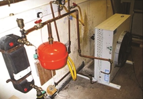
Figure 3: Shows the connections of the heat exchanger, water pump, heat rejection fan and expansion valve.

Figure 4: Shows the connections of the heat exchanger and expansion valve.

Figure 5: Shows the power supply to heat injection fan
The concept of multi-scale heat exchanger is expected to have the following characteristics:
- A relatively significant specific heat exchange surface compared to that of traditional exchangers;
• A high heat transfer coefficient, as heat transfer is taking place at micro-scales and meso-scales;
• An optimised pressure drop equally distributed between the various scales;
• A modular character, allowing assembly of a macro-scale exchanger from microstructured modules.
Some difficulties still exist. On the one hand, the properties of flow distribution in such an exchanger are still unknown. A lot of research work still needs to be done for the equidistribution optimisation. On the other hand, 3-D modelling of heat transfer for such an exchanger requires a thorough knowledge of the hydrodynamics and profound studies on elementary volume (smallest scale micro channels). Finally, maintenance problems for this type of integrated structures may become unmanageable when fouling; corrosion, deposits or other internal perturbations are to be expected. Figures 2-4 show the connections of the heat exchanger, water pump, heat rejection fan expansion valve, and the power supply to heat injection fan (Figure 5).
Renewable energy is the term to describe a wide range of naturally occurring, and replenishing energy sources. The use of renewable energy sources and the rational use of energy are the fundamental inputs for a responsible energy policy. The energy sector is encountering difficulties because increased production and consumption levels entail higher levels of pollution and eventually climate changes, with possibly disastrous consequences. Moreover, it is important to secure energy at acceptable cost to avoid negative impacts on economic growth. On the technological side, renewables have an obvious role to play. In general, there is no problem in terms of the technical potential of renewables to deliver energy and there are very good opportunities for renewable energy technologies to play an important role in reducing emissions of greenhouse gases into the atmosphere-certainly far more than have been exploited so far. However, the biggest problem with replying on renewables to deliver the necessary cuts in greenhouse gas emissions is more to do with politics and policy issues than with technical ones.
The single most important step governments could take to promote and increase the use of renewables would be to improve access for renewables to the energy market. That access to the market would need to be under favourable conditions and possibly under favourable economic rates. One move that could help-or at least justify-better market access would be to acknowledge that there are environmental costs associated with other energy supply options, and that these costs are not currently internalised within the market price of electricity or fuels. It could make significant difference, particularly if, appropriate subsidies were applied to renewable energy in recognition of environmental benefits it offers. Cutting energy consumption through end-use efficiency is absolutely essential. And this suggests that issues of end-use consumption of energy will have to come onto the table in the foreseeable future.
Thermal comfort is an important aspect of human life. Buildings where people work require more light than buildings where people live. In buildings where people live the energy is used for maintaining both the temperature and lighting. Hence, natural ventilation is rapidly becoming a significant part in the design strategy for non-domestic buildings because of its potential to reduce the environmental impact of building operation, due to lower energy demand for cooling. A traditional, naturally ventilated building can readily provide a high ventilation rate. On the other hand, the mechanical ventilation systems are very expensive. However, a comprehensive ecological concept can be developed to achieve a reduction of electrical and heating energy consumption, optimise natural air condition and ventilation, improve the use of daylight and choose environmentally adequate building materials. Energy efficiency brings health, productivity, safety, comfort and savings to homeowner, as well as local and global environmental benefits. The use of renewable energy resources could play an important role in this context, especially, with regard to responsible and sustainable development. It represents an excellent opportunity to offer a higher standard of living to local people and will save local and regional resources. Implementation of the ground source heat pump systems offers a chance for maintenance and repair services. It is expected that the pace of implementation will increase and the quality of work to improve in addition to building the capacity of the private and district staff in contracting procedures. The financial accountability is important and more transparent.
Various passive techniques have been put in perspective, and energy saving passive strategies can be seen to reduce interior temperature and increase thermal comfort, and reducing air conditioning loads. The scheme can also be employed to analyse the marginal contribution of each specific passive measure working under realistic conditions in combination with the other housing elements. In regions where heating is important during winter months, the use of top-light solar passive strategies for spaces without an equator-facing façade can efficiently reduce energy consumption for heating, lighting and ventilation. The use of renewable energy resources could play an important role in this context, especially, with regard to responsible and sustainable development. It represents an excellent opportunity to offer a higher standard of living to local people and will save local and regional resources. Implementation of the GSHPs offers a chance for maintenance and repair services.
An annual sinusoidal ambient temperature profile and an exponentially decaying sinusoidal temperature profile as a function of depth are assumed. Temperature at any given depth in a moment can be estimated on the basis of the following equation.
 (4)
(4)
where:
T(x, t) is the soil temperature at the depth (x) and time (t) (oC), Tm is an average soil temperature (oC), As is the thermal wave amplitude (oC), x is the depth (m), t is the day of year (in days, where t=0 at midnight on 31 December), to is the phase constant (days), and α is the apparent thermal diffusivity (m3/day).
The heat exchanger effectiveness is defined as the ratio of actual heat transfer versus maximum possible heat transfer. The actual heat transfer may be computed by calculating either the energy lost by the hot fluid or the energy gained by cold fluid. For counter flow and parallel flow heat exchangers it is given as:
Q = (mcp) h (Th, in-Th, out)
= (mcp) c (Tc, out-Tc, in) (5)
The maximum possible heat transfer expressed as:
Q = (mcp) min (Th, in-Tc, in) (6)
The minimum fluid may be either the hot or cold fluid, depending on the mass flow rates and specific heats. For counter flow heat exchanger, the effectiveness is given as:
 (7)
(7)
For given effectiveness and maximum heat transfer rate, actual heat transfer rate be obtained from:
![]() (8)
(8)
The number of heat transfer units designates the non dimensional heat transfer size of the heat exchangers is defined as:
NTU = UA/Cmin (9)
Defining capacity rate as the product of mass flow rate and specific heat as:
(mCp) c = Cc and (mCp) h = Ch (10)
According, Cmin and Cmax will be minimum and maximum capacity rate respectively. The relationship between effectiveness and number of heat transfer units, NTU is given for counter flow heat exchanger configuration as follows:
![]() (11)
(11)
Compared to the LMTD method of analysis of heat exchanger, effectiveness- NTU method provides a direct solution. LMTD method requires the outlet temperature of both the streams which is not so in effectiveness- NTU method.
Thermodynamic Efficiency Analysis of Heat Exchanger
The maximum useful work that could be obtained from the system at a given state in a specified environment is known as exergy also called available energy. The property exergy serves as a valuable tool in determining the quality of energy and comparing work potential of different energy sources or systems. From the second law point of view, a measurement procedure is required to compare the performance of different processes or equipment.
The type of exergy efficiency called the rational efficiency is defined by Kotas, 1985 as the ratio of desired exergy output to exergy used:
 (12)
(12)
Ψ is the sum of all exergy transfers from the system, which must regarded as constituting the desired output, plus any by-product, which is produced by the system. The desired output is determined by examining the function of the system. Eused is the required exergy input for the process to be performed which can be expressed in terms of irreversibilities as:
![]() (13)
(13)
Alternative form of the rational efficiency can be obtained from:
 (14)
(14)
From the consideration of the heat exchanger, Kotas considered that the desired exergy output as the increase of the thermal component of exergy of the cold stream:
![]() (15)
(15)
where:
![]() (16)
(16)
with reference to equation (12), in which rational efficiency is formulated, the following identify the required exergy input, Eused as:
![]() (17)
(17)
By using equation (12) and equation (14), the rational efficiency of the heat exchanger is obtained as:
 (18)
(18)
The exergy change of the hot and cold streams can be written with the help of ideal gas relations as follows:
Eout – Ein = m [hout – hin + To (sout – Sin)]
= mCp (Tout – Tin) – To mCp Ln (Tout/Tin) + mToR Ln (Pout/Pin) (19)
The desired exergy output which is the increase of the thermal component of exergy of the cold stream is obtained by equation (19) as:
 (20)
(20)
Expressing the outlet temperature in terms of inlet temperature and effectiveness from equation (7), the above equation becomes:
 (21)
(21)
The irreversibility, also called exergy destruction or exergy loss, is calculated by exergy balance and taking the difference between all incoming and outgoing exergy flows given by Kotas, 1985:
I = ∑ Ein-∑Eout (22)
Another way of calculating the irreversibility can be done by the Gouy-Stodola formula, in which the entropy generation rate is multiplied by the environmental temperature as:
I = To Sgen (23)
which, in turn can be written in terms of summation of irreversibilities due to temperature difference between the fluid streams and pressure drop respectively as:
![]() (24)
(24)
The entropy generation rate in the heat exchanger is formulated using first and second law statements:
I = I∆T + I∆P (25)
Defining entropy generation number by dividing entropy generation by minimum heat capacity, i.e., Cmin as given by:
Ns = Sgen/Cmin (26)
This number is second-law ‘relative’ of the order concept of the NTU, which is used in traditional first-law analyses of heat exchangers. Ns represent a high or a low entropy generation rate depends on the following factors:
- The size of heat exchanger Ns that can be economically tolerated;
• On the magnitude of the remnant irreversibility, Ns, imbalance;
• On the entropy generation levels shown by the other components that make up the greater system.
Heat exchangers are generally inefficient from an energy conservation point of view because they have been designed in the past on the basis of low cost that dictates a minimum-size unit. To achieve the small-size heat exchanger, the temperature difference between the fluid streams is maximised.
However, the larger is the temperature difference in a heat exchanger, the greater will be the loss during heat transfer. Also, capacity mismatch is used between the streams to increase the performance.
Stored Energy
Thermal (internal) energy is caused by the motion of molecules and/or intermolecular forces. Potential energy (PE) is caused by attractive forces existing between molecules, or the elevation of the system.
PE = mgz (26)
where: m is the mass; g is the local acceleration of gravity; and z is the elevation above horizontal reference plane.
Kinetic energy (KE) is the energy caused by the velocity of molecules and is expressed as:
KE = ½mV2 (27)
where: V is the velocity of a fluid stream crossing the system boundary.
Flow work is energy carried into or transmitted across the system boundary because a pumping process occurs somewhere outside the system, causing fluid to enter the system. Flow work also occurs as fluid leaves the system (Figure 6).
Flow work (per unit mass) = pv (28)
Enthalpy h is an important property that includes internal energy and flow work and is defined as:
h = u + pv (29)
First Law of Thermodynamics
The first law of thermodynamics is often called the law of conservation of energy. The following form of the first-law equation is valid only in the absence of a nuclear or chemical reaction.
Based on the first law or the law of conservation of energy for any system, open or closed, there is an energy balance as:
[Net amount of energy added to system] = [Net increase of stored energy in system] (30)
or
[Energy in] – [Energy out] = [Increase of stored energy in system] (31)
For the general case of multiple mass flows with uniform properties in and out of the system, the energy balance can be written:
 (32)
(32)
where subscripts i and f refer to the initial and final states respectively.
Nearly all important engineering processes are commonly modelled as steady-flow processes. Steady flow signifies that all quantities associated with the system do not vary with time. Consequently:
 (33)
(33)
where: h = u +pv as described in equation (48).
A second common application is the closed stationary system for which the first law equation reduces to:
Q – W = [m (uf – ui] system (34)

Figure 6: Energy flows in general thermodynamic system.
Second Law of Thermodynamics
The second law of thermodynamics differentiates and quantifies processes that only processed in a certain direction (irreversible) from those that are reversible. Reducing total irreversibility in a cycle improves cycle performance. In the limit of no irreversibilities a cycle attains its maximum ideal efficiency. In open system, the second law of thermodynamics can be described in terms of entropy as:
 (35)
(35)
where: dSsystem is the total change within system in time dt during process; δmisi is the entropy increase caused by mass entering (increasing); δmese is the entropy decrease caused by mass leaving (exiting); δQ/T is the entropy change caused by reversible heat transfer between system and surroundings at temperature T; dI is the entropy change caused by irreversibilities (always positive).
Equation (35) accounts for all entropy changes in the system, Rearranged, this equation becomes:
![]() (36)
(36)
Thermodynamics and Refrigeration Cycles
In integration form, if inlet and outlet properties, mass flow and interactions with the surroundings do not vary with time, the general equation for the second law is:
 (37)
(37)
In many applications, the process can be considered to operate steadily with no change in time. The change in entropy of the system is therefore zero. The irreversibility rate, which is the rate of entropy production caused by irreversibilities in the process, can be determined by rearranging equation (37):
 (38)
(38)
Equation (37) is commonly applied to a system with one mass flow in, the same mass flow out, no work and negligible kinetic or potential energy flows, combining equation (33) and (37) yields:
 (39)
(39)
In a cycle, the reduction of work producing by a power cycle (or the increase in work required by a refrigeration cycle) equals the absolute ambient temperature multiplied by the sum of irreversibilities in all processes in the cycle. Thus, the difference in reversible and actual work for any refrigeration cycle, theoretical or real, operating under the same conditions, becomes:
 (40)
(40)
Thermodynamic Analysis of Refrigeration Cycles
Refrigeration cycles transfer thermal energy from a region of low temperature TR to one of higher temperature.
Usually the higher temperature heat sink is ambient air or cooling water, at temperature To, the temperature of the surroundings. The first and second laws of thermodynamics can be applied to individual components to determine mass and energy balances and the irreversibility of components.
Performance of a refrigeration cycle is usually described by a coefficient of performance (COP), defined as the benefit of the cycle (amount of heat removed) divided by the required energy input to operate the cycle:
![]() (41)
(41)
where: Ue is the useful refrigeration effect, and Ne is the net energy supplied from external sources.
 (42)
(42)
In an absorption refrigeration cycle, the net energy supplied is usually in the form of heat into the generator and work into the pump and fans, or:
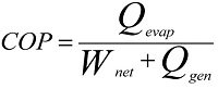 (43)
(43)
In many cases, work supplied to an absorption system is very small compared to the amount of heat supplied to the generator, so the work term is often neglected. Applying the second law to an entire refrigeration cycle shows that a completely reversible cycle operating under the same conditions has the maximum possible COP. Departure of the actual cycle from an ideal reversible cycle is given by the refrigerating efficiency:
 (44)
(44)
The Carnot cycle usually serves as the ideal reversible refrigeration cycle. For multistage cycles, each stage is described by a reversible cycle.
Conclusion
The building sector is a major consumer of both energy and materials worldwide, and the consumption is increasing. Most industrialised countries are in addition becoming more and more dependent on external supplies of conventional energy carriers, i.e., fossil fuels. Energy for heating and cooling can be replaced by new renewable energy sources. New renewable energy sources, however, are usually not economically feasible compared with the traditional carriers. In order to achieve the major changes needed to alleviate the environmental impacts of the building sector, it is necessary to change and develop both the processes in the industry itself, and to build a favourable framework to overcome the present economic, regulatory and institutional barriers. Today, buildings are largest consumers of energy. Air conditioning and heating consume about 40% of the power in the buildings. Demand to conserve energy has become necessity as there has been rising costs of energy consistently and this make us to think to go green and innovate the greener concept for buildings. A green building uses less water, optimises energy efficiency, conserves natural resources, generates less waste and provides healthier spaces for occupants. And, a green home can have benefits, such as reduction in water and operating energy costs of the building. This may also mean refrigerant-based chillers and compressors to be shut off or to be operated at reduced capacity. With the environmental protection posing as the number one global problem, man has no choice but reducing his energy consumption, one way to accomplish this is to resort to passive and low-energy systems to maintain thermal comfort in buildings.
Naturally, it would be preferred, for comfort reasons that this index would be small, preferably nil. It may be seen that the variable is directly related to temperature discomfort: the larger the value of the index, the farthest will inside conditions be from expected wellbeing. Also, the use of electricity operated air conditioning systems will be more expensive the higher this variable is. Hence, energy expenditure to offset discomfort will be higher when comparing two index values; the ratio of them is proportional to the expected energy savings. When the external shade blocks the windowpane completely, the excessive heat gains belong to the lowest values in the set, and the dimensionless index will be constant with orientation. For the climate conditions of the locality, it can be seen that a naked window can produce undesirable heat gains if the orientation is especially unfavourable, when the index can have an increase of up to 0.3 with respect to the totally shaded window.

If you want to share thoughts or feedback then please leave a comment below.


Muchas gracias. ?Como puedo iniciar sesion?