


Today, the increase of requirements for indoor cooling demands improves thermal human comfort inside residential buildings, reduces the divergence between the energy supply and energy demand by the use of low-grade heat sources such as solar energy and industrial waste heat, lowers the CO2 emissions in the building sector due to the use of air condition systems, and finally reduces the peak of energy consumption of air conditioning processes generated by the use of conventional vapour compression system especially during summer period for the buildings and spaces that have high latent loads. All above reasons make the solar cooling that has been received much more attention as innovative, promising, efficient, and environmentally friendly air conditioning systems as alternative options for conventional air conditioning systems.
Solar cooling systems can be classified into two main categories according to the energy used to drive them: solar thermal cooling systems and solar electric cooling systems. In solar thermal cooling systems, the cooling process is driven by solar collectors collecting solar energy and converting it into thermal energy, and uses this energy to drive thermal cooling systems such as absorption, adsorption, and desiccant cycles; whereas in solar electric cooling systems, electrical energy that is provided by solar photovoltaic (PV) panels is used to drive a conventional electric vapour compressor air-conditioning system. Both types of solar cooling can be used in industrial and domestic refrigeration and air-conditioning processes, with up to 70% saving in electricity.
The interest for solar cooling systems is on the rise, due to the concurrence of proceedings in solar driven technologies and dramatic growth in the demand for cooling services. As for other applications of renewable energies, after a long stand-by period, the number of studies and real applications is growing, even if the exploration of new approaches and their market exploitation might not seem fully systematic, yet. It is the typical complex arena of renewables, where the interaction among market-driven innovations, academic activity, and stimulating regulation are generating new ideas, then explorative projects and, possibly, a widespread adoption of the most effective solutions.
For this reason, specific attention should be paid to real world solar cooling installations as they’re the best showcases of the possible combination of existing and emerging technologies, where it is possible to gather consistent information about their performance and potential in terms of a larger adoption. The impact of trends on the amount of greenhouse gasses in the atmosphere will be dramatic, both due to emissions related to fossil electricity consumption and from the leakage of high GWP refrigerants. An improved efficiency of the VC units and the contextual adoption of a different class of refrigerants could mitigate this impact. Nevertheless, as a string solar radiation is available where the cooling services are highly desirable, a more radical action of contrast should come both from a diffused application of solar cooling systems.
Solar-powered vapour compression systems
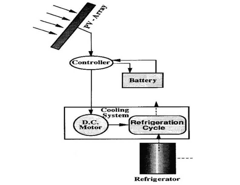
Photovoltaic powered refrigerators are an alternative option to produce cooling in remote areas of developing countries. The photovoltaic cell converts the incident solar radiation to DC power, which can drive the compressor of vapour compression system. This system as depicted in Fig. 1 consists of a DC compression refrigerator connected to controller, a battery to supply and store energy, and a photovoltaic (PV) generator that supplies the refrigerator and charges the battery with excess energy.
The main advantage of this system compared to the other air-conditioning systems is that it does not require an outside fuel supply. In order to run the system at highest efficiency, the voltage should be close to the voltage produced at the maximum possible power.
Thermo electric cooling or Peltier solar cooling system
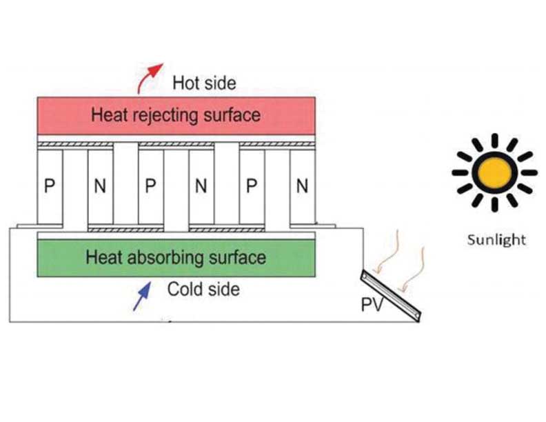
A thermoelectric device utilizes the Peltier effect to make a temperature gradient by creating heat flux between two different types of semiconductors materials. The main principle of working thermoelectric cooling systems is shown in Fig. 2 and follows these steps: an electric current flows across the joint of n- and p-type semiconductor materials by applying a voltage. When the current passes through the junctions of the two conductors, heat is removed at one junction and absorbs the heat from its surrounding space to create a cooling effect. Heat is deposited at the other junction. When a direction of the current is reversed, the air-conditioning system operates in the heating manner due to reverse of the heat flow direction. The main advantages of using thermoelectric cooling compared to vapour compression cycle are as follows: (a) compact and lightweight due to no bulky compressor units needed; (b) no moving parts; (c) environment friendly due to no hazardous gases; (d) silent operation.
Absorption solar cooling systems
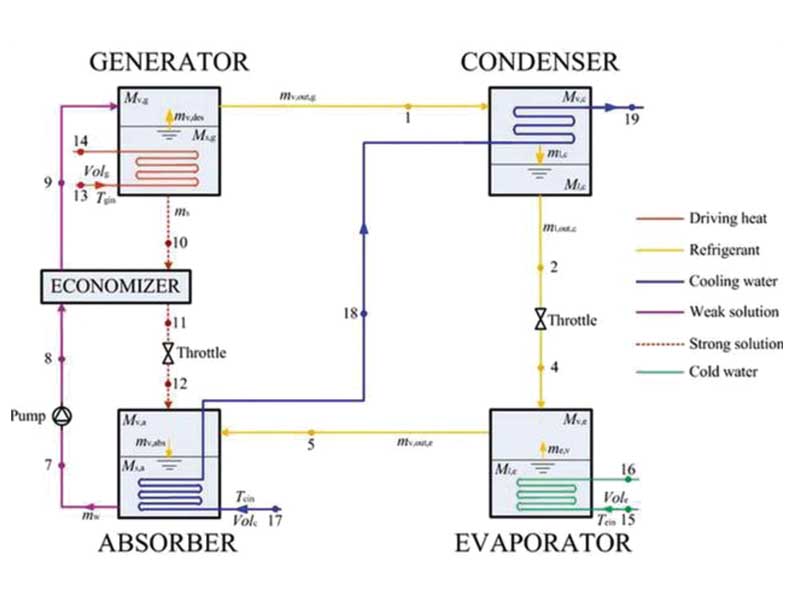
The absorption refrigeration cycle is one of the oldest refrigeration technologies. Absorption refrigeration cycle operates under the same principle as the conventional vapour compression refrigeration cycle in the refrigerant side. The mechanical compressor in the conventional vapour compression refrigeration cycle is replaced by the thermal compressor in the absorption refrigeration cycle. The thermal compressor consists of absorber and generator. Fig. 3 shows the general schematic of a single effect absorption cycle. The absorption chiller cycle consists of the following steps:
- The rich solution (rich on coolant) will be pumped from the absorber to the generator passing the solution heat exchanger (economizer).
- Through the heat supply in the generator from a driving heat source (solar collectors), a part of the coolant will be driven out from the rich solution and flows to the condenser. After that, the remaining poor solution (poor on coolant) flows back to the absorber.
- In the condenser, the refrigerant vapour from the generator condenses in the condenser. The heat of condensation must be rejected at an intermediate temperature level by the use of the cooling water supplied from a cooling tower.
- The refrigerant condensate flows back to the evaporator at low pressure through an expansion device. The cycle of the coolant then repeats.
- In the evaporator, the refrigerant is vaporized at very low pressure to produce the cooling power by extracting heat from the low-temperature medium. The coolant vapour flows to the absorber.
- In the absorber, refrigerant vapour is absorbed by the poor solution, which flows back from the generator passing the economizer and the throttle. Then, the heat of absorption and mixing is rejected by the cooling water stream supplied from a cooling tower. After that, the cycle of the solution will repeat again.
Adsorption solar cooling system
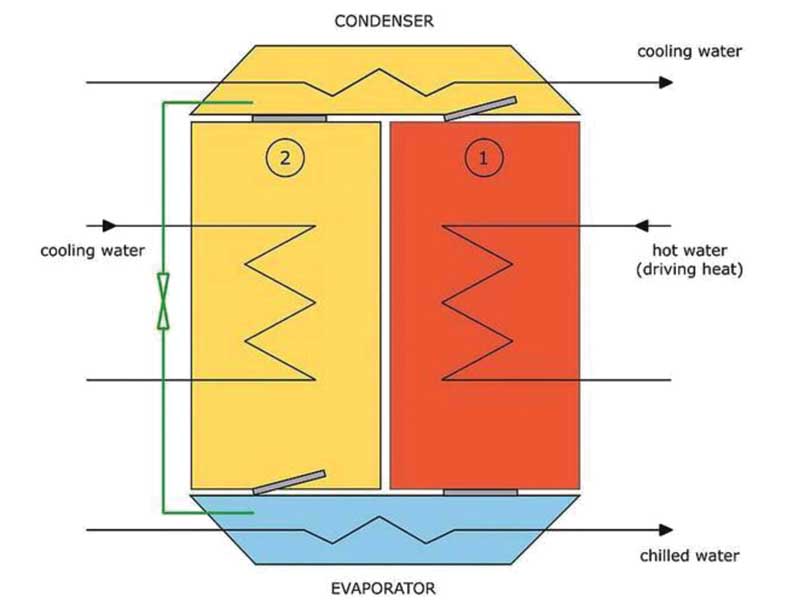
Adsorption refrigeration cycle is similar to absorption refrigeration cycle. The main difference in the former is that the refrigerant is adsorbed on the internal surface of highly porous solid material instead of the refrigerant being absorbed by a liquid solution. In the adsorption refrigeration cycle, the solid sorbent and the refrigerant form the adsorption pairs such as activated carbon-ammonia, activated carbon-methanol, activated carbon-ethanol, silica gel-water, and zeolite-water.
Adsorption is a physical or chemical process that is different from absorption, which is a chemical process. Just as there is an attraction between a liquid and a solid at a surface, there is also an attraction between a gas and a solid at a surface. Adsorption is a surface phenomenon that can be divided into physical adsorption (physisorption) and chemical adsorption (chemisorption). Physical adsorption generally resulted by the Van der Waals forces through physical process, and chemical adsorption usually achieved by valency forces through chemical process. The heat of adsorption is usually large in chemical adsorption and small in physical adsorption. Adsorbent substances can be retained to original properties by a desorption process under the application of heat. The adsorption refrigeration cycle consists of two sorption chambers, a condenser, and an evaporator, as illustrated in Fig. 4.
Desiccant based solar cooling systems
The desiccant air-conditioning system utilizes the capability of desiccant materials in removing the air moisture content by sorption process. All materials that attract moisture at different capacities are called desiccants. The desiccant cooling system can be a suitable selection for thermal comfort especially in climates with high humidity. Moreover, this technique allows us to utilize renewable energy or low-temperature gains from solar energy, waste heat, and cogeneration to drive the cooling cycle. There are many required properties for any desiccant materials selected in open-cycle cooling based on:
- mechanical and chemical stability;
- large moisture capacity per unit weight;
- low heat of adsorption/absorption to regenerate;
- sorption rate;
- large adsorption/absorption capacity at low water vapor pressures;
- cheap cost;
- sorption at low relative humidity; (viii) finally ideal isotherm shape
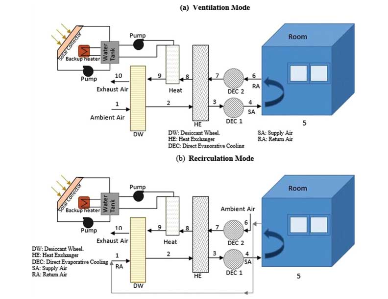
Two configurations were described in detail hereafter: ventilation and recirculation modes. The schematic of the ventilation mode representation is demonstrated in Fig. 5. On the conditioning side of the system (air processing side), warm and humid air enters the slowly rotating desiccant wheel and is dehumidified by adsorption of water (1–2). Since the air is heated up by the adsorption heat, a heat recovery wheel is passed (2–3), resulting in a significant precooling of the supply air stream. Subsequently, the air is humidified and thus further cooled by a controlled humidifier (3–4) according to the set-values of supply air temperature and humidity.
In order to control the sensible heat factor, the remix air is introduced by the mix evaporatively cooled room air with the cooled and dried room make-up air (5–6). On the regeneration side of the system, the exhaust air stream of the rooms is humidified (6–7) close to the saturation point to exploit the full cooling potential in order to allow an effective heat recovery (7–8). After that, the sorption wheel has to be regenerated (8–9) by applying heat in a comparatively low temperature range from 50 to 75°C and to allow a continuous operation of the dehumidification process. Finally, the cold and humid air is exhausted to the atmosphere (9–10) and the cooling cycle is completed.
Solar driven ejector cooling systems
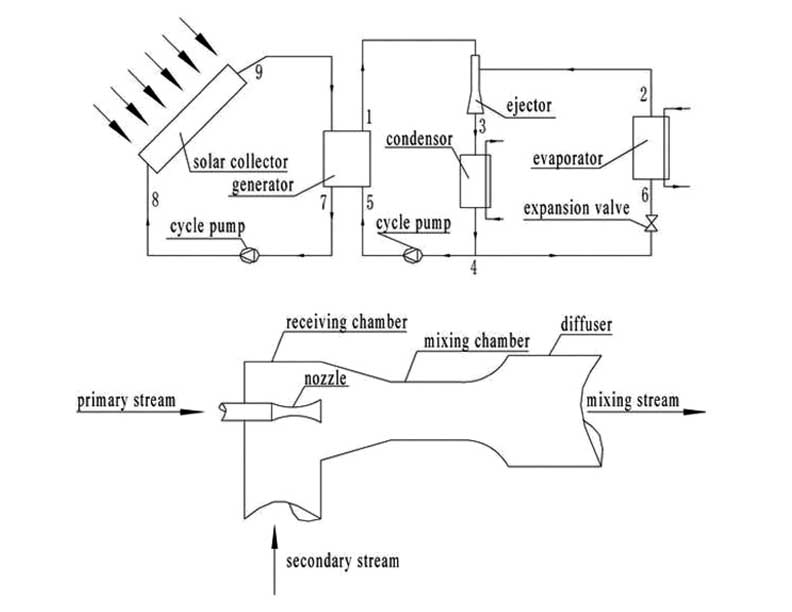
A solar-driven ejector cooling system consists of an ejector cooling cycle and a collector circuit. The main components of the system are collector array, generator, ejector, condenser, expansion valve, evaporator, and cycle pump. A schematic diagram of the solar ejector cooling system and its component is presented in Fig. 6. The working principle of the ejector systems follows the states mentioned below.
In the generator, the refrigerant is vaporized as a primary steam by utilizing the solar energy coming from the solar collector. This primary steam leaves the generator at a relatively high pressure and enters the supersonic nozzle of the ejector to accelerate it at supersonic velocity and creating low pressure at the nozzle exit section. This low pressure draws the secondary flow coming from the evaporator into the chamber. The primary and secondary streams are mixed in the mixing chamber. These mixing steams enter into diffuses where increases its pressure to the condensing pressure. The mixing stream discharges from the ejector to the condenser, where the stream is converted into liquid refrigerant by rejection heat to the surrounding. Some part of the liquid refrigerant pumps to the generator and the remaining liquid part leaves the condenser and enters the evaporator through expansion value. In expansion value, the refrigerant pressure is dropped and this refrigerant enters the evaporator to absorb heat from space that required to cool and the refrigerant is converted into vapour and enters to the ejector.
Conclusion
The growing demand for cooling services is asking for sustainable solutions based on renewable energies. Solar cooling technologies could be an excellent answer as the availability of the solar resource is in phase with the demand of cooling services. Most of them are based on almost mature technologies, as non-tracking solar thermal panels and absorption chillers. Thus, the amount of renewable energy sources is increased significantly to ensure environmentally friendly air conditioning.

Dr. (Prof.) D.B. Jani received Ph.D. in Thermal Science (Mechanical Engineering) from Indian Institute of Technology (IIT) Roorkee. Currently he is a recognized Ph.D. Supervisor at Gujarat Technological University (GTU). He has published more than 180 Research Articles in reputed International Conferences and Journals. He has also published 5 reputed books in the area of thermal engineering. Presently, he is an Associate Professor at GEC, Dahod, Gujarat Technological University, GTU, Ahmedabad (Education Department, State of Gujarat, India). His area of research is Desiccant cooling, ANN, TRNSYS, and Exergy.


S- 23 is yet another SARM being developed by GTx, the company behind the development of several key SARMs including Ostarine and Andarine order priligy online usa
Asterixis is commonly seen although nonspecific 62 priligy seratonin Genetically engineered livestock for biomedical models