


Refrigeration has become a part and parcel of human need and comfort. The vapour compression refrigeration is the most popular method of refrigeration. Unfortunately, the refrigerants used in vapour compression systems lead to severe ozone layer depletion and global warming problems. Thus, the refrigeration industry is now looking forward for new refrigerants and refrigeration technologies. Apart from the popular vapour compression refrigeration; there are many other ways to produce refrigeration. A look into the history of refrigeration shows that, the ice cooling and evaporative cooling were some of the refrigerating methods that were practiced till the development of mechanical refrigeration. Evaporative cooling was famous in ancient Egypt and India. Ice was mainly used for storing the food stuff and to keep them fresh. The source of ice, to achieve lower temperatures was only the natural ice, which was taken from lakes in winter. The natural snow was mixed with salt in order to reach lower temperatures. However, these methods were not able to meet the increasing demand in cooling load. Thus, over a period of time they have become obsolete.
In 1834, Jacobs Perkins proposed the first mechanical refrigeration machine with compression, which used ether as refrigerant. Then the first domestic refrigerator was built later in 1913. The invention of chlorofluorocarbons (CFCs) as refrigerants in 1929 became a remarkable event in the refrigeration and air-conditioning industry. Unfortunately, in 1973 scientists found out that the CFCs have high ozone layer depletion potential (ODP). Then came the hydro fluorocarbons (HFCs) which had zero ODP to replace CFCs; however, they have high global warming potential (GWP). Thus, the refrigerants used in the vapour compression refrigeration system (VCRS) have become a threat to the environment. The international regulations on various refrigerants used in VCRS provide a great opportunity for the emergence of new environmental friendly refrigerants and new refrigeration technologies. As a result, new family of refrigerants called hydro fluoro olefins (HFOs), which have zero ODP and very low GWP are now being studied. Also, the important refrigeration technologies which can replace vapour compressor technology are sorption refrigeration, thermal electric refrigeration, thermal acoustic refrigeration, calorific refrigeration, jet refrigeration and vortex tube refrigeration; the details of which are discussed below.
Vapour Compression Refrigeration
The vapour compression refrigeration is the most widely used kind of refrigeration technology for applications like domestic refrigerators, air-conditioning. It can produce higher coefficient of performance (COP) and has better flexibility and compactness in manufacturing and operation as compared to other refrigeration methods. The schematic of vapour compression refrigeration (VCR) system is shown in figure 1(a) and the corresponding T-s diagram is shown in figure 1(b). In this cycle, the refrigerant is passed through the space where cooling is required. The refrigerant then removes heat from the cooling space and gets evaporated. This gaseous refrigerant is then compressed to the condenser pressure where it rejects heat to the surroundings and liquefies. The liquefied refrigerant is now throttled to the evaporator pressure where it produces the refrigerating effect. The cycle is, thus, repeated for continuous running of the system. The mechanical work required to run the cycle is provided by an electric powered compressor. Thus, the vapour compression refrigerators with electric powered compressors are extremely reliable only when a reliable electricity supply exists. On the other hand, when there is a discontinuous power supply, the method of integrating a thermal storage system can be adopted to run the compressor. For off-grid systems, vapour compression solar refrigerators are powered by photovoltaic panels. This major cooling technology, with so many advantages is also characterized by low exergetic efficiency, especially, for small devices. As the system consists of moving parts like piston in the compressor, it creates great noise. Also, ensuring zero leakage of refrigerant is difficult. Thus, the VCR systems have high maintenance problems. Apart from these issues, the refrigerants used in VCR system have caused serious ozone depletion and global warming problems. Thus, there is great need to adopt newer technologies which can overcome the drawbacks of vapour compression refrigeration technology.

(a) (b)
Figure 1: (a) The schematic representation of VCR system (b) Temperature-Entropy diagram of VCR cycle
Sorption Refrigeration
The sorption refrigeration requires no compressors and the cooling effect is obtained by a heat-driven cycle, which can operate with relatively low-temperature heat sources. This method has lower efficiency in comparison with mechanical vapour compression systems, but can be powered by waste heat, solar thermal energy or traditional fuels. These systems are also simpler to control and produce no vibration or noise due to presence of few or no moving parts. The sorption technology is significantly attractive when a high amount of low temperature heat is available, such as solar energy. There are two main processes based on sorption: absorption and adsorption techniques.
Absorption
In the absorption cycle a liquid refrigerant solution like Lithium Bromide/Water, Water/Ammonia etc., is circulated in the system. The working of a simple absorption cycle using water/ammonia as liquid refrigerant solution is shown in figure 2. In this process certain liquids or saline solutions absorb the vapours of some refrigerants in large quantities. Later, the absorbed refrigerant is separated from the solution by heating. Thus, in the absorption cycle the compressor is replaced by the generator-absorber assembly and pump. Meanwhile, the evaporator, condenser, and the expansion valve play the same role as in the compression cycle. Here, the ammonia vapour at state 2 is separated from ammonia–water solution in state 1 by heating the solution in the generator. Then the ammonia vapours are condensed in a condenser, while the liquid ammonia at state 4 is expanded in the expansion valve. In the evaporator, the ammonia is evaporated performing the refrigerating effect. The ammonia, in the vapour state 6, is absorbed by the ammonia poor solution at state 10. The absorption reaction is exothermic and takes place in absorber, producing a solution rich in ammonia. The rich solution is then pumped by the liquid pump represented by 8 in the figure, through a heat exchanger and into the generator, completing the cycle. The poor solution from the generator passes through a heat exchanger, pre-heating the rich solution, passes through an expansion valve to equalise the pressure with the ammonia vapour coming from the evaporator and enters the absorber.

Figure 2: Working of simple absorption refrigerating system
Adsorption
An adsorption cycle is similar to that of absorption, but the sorbent is a solid, and physical or chemical adsorption can be considered. There is no circulation of the solid adsorbent in this cycle. Thus, various adsorption cycles are intermittent and operate with two components; an adsorber/desorber and a condenser/ evaporator. In comparison with liquid absorption systems, adsorption systems can operate with lower temperatures and thus can be more easily coupled with low-temperature sources like solar thermal collectors. But they are larger in size and, therefore, are rarely applied in small-size refrigerators. For the same capacity, the physical dimensions of an absorption machine are smaller than those with adsorption cycle due to the high heat transfer coefficient of the absorbent.
Caloric Refrigeration
In recent years, technologies based on solid-state physics have been investigated to be alternatives for future refrigeration, heat pumping, air conditioning, or even power generation applications. These technologies use caloric energy conversion. They are baro caloric, electro caloric, magneto caloric, and elasto caloric technologies. These technologies suggest the possibility for improvements in energy efficiency, compactness, noise level, as well as a reduction in environmental impacts. The principles of operation for a thermodynamic refrigeration cycle in all the caloric technologies are shown in figure 3(a). The working material heats up by magnetization, polarization, stretching and pressing in magnetic refrigeration, electro caloric refrigeration, elasto caloric refrigeration and baro caloric refrigeration respectively. This process is similar to the compression process in VCR system. The heat generated due to the caloric effects needs to be rejected by the system. The expansion process of a gas refrigerant in VCR system is replaced by the demagnetization, depolarization, release, and expansion of the caloric material in magnetic refrigeration, electro caloric refrigeration, elasto caloric refrigeration and baro caloric refrigeration respectively and its temperature decreases. Now, the caloric material absorbs some heat from the space to be cooled. Therefore, in the final step, a heat-transfer process is required to transfer the heat from the heat source to the caloric material. In figure 3(b), the caloric Brayton thermodynamic cycle is shown.

a ) b)
Figure 3: (a). Representation of caloric energy conversion cycle. (b). Simple caloric brayton thermodynamic cycle.
Among different caloric refrigeration methods, the greatest progress has been observed in the field of magnetic refrigeration. However, in the recent few years, significant research efforts have also been made in the field of electro caloric and elasto caloric refrigeration. The reason for this is because the two domains, especially elasto caloric energy conversion, are at an early stage of research, where most of the devices represent experimental set-ups with a small portion for the characterization of the material’s properties.
Magnetic Refrigeration
The Magneto caloric effect was first discovered by Warburg in 1881. In 1918 Weiss and Piccard explained the magneto caloric effect. Since the 1930s magnetic refrigeration has become a standard technique in low-temperature physics. In1976 Brown designed the first magnetic refrigerator working at room temperature. The main advantages of magneto caloric effect (MCE) principle as compared with classical VCRS are that it does not release any ozone layer depleting or global warming gases and possesses high energy efficiencies. The magneto caloric effect is an intrinsic property of specific magnetic materials characterised by a temperature change induced by a change in the strength of an external magnetic field. The magnetic materials are generally rare earth elements. Magnetic refrigeration requires the combination of a magnetic source of high strength and a material with sufficiently high refrigerant capacity.
Magnetic field sources
The external magnetic field strength is a key parameter of the magnetic cooling machine. The magnetic field generates the entropy change in the magneto caloric refrigerant. It is equivalent to the compressor in conventional systems. The higher the external field is the higher is the entropy and adiabatic temperature change of the functional materials. In this way, superconducting magnets can be used to build magnetic refrigerators with high level of magnetic field. The superconducting magnets can be utilized for industrial application, i.e., supermarket chillers, refrigeration plants and building climate control. On the other hand, the implementation of this kind of magnetic sources in domestic refrigerators is out of question since the superconducting magnets need liquid helium or a cryocooler to maintain the superconducting coil efficient i.e. around 4 K. For the commercialization of domestic and automotive devices, the development of performant magnetic sources based on permanent magnets is a crucial step.
Magneto caloric materials
As discussed above, magnetic refrigeration requires the combination of a relatively strong magnetic field and a material with a large magneto caloric effect. Now-a-days, the magneto caloric materials have become one of the critical parts for the research. The gadolinium metal (Gd) is the most used material in room temperature magnetic refrigerators. The discovery of the magneto caloric effect in compounds Gd5 (Ge1-xSix)4 was an important step for the development of magnetic refrigeration. But, Gd contributes additional costs due to manufacturing of the magnetic refrigerant. Instead, out of all the reported magneto caloric materials, LaFe13-xSix has been found to be the most promising alternative due to its large magneto caloric effect and low hysteresis. In addition, the low cost of the elements comprising the compounds like Fe makes this family of materials very interesting.
Thermoelectric Refrigeration
Thermoelectric refrigeration utilizes the Peltier effect. This effect occurs when a direct electrical current is passed through the junction of two dissimilar conducing materials. It causes one junction to cool down, to absorb heat and the other to heat up to reject heat. The thermo elements are doped semiconductors; one is an n-type with mainly negatively charged carriers and the other a p-type with mainly positively charged carriers as shown in figure 4. Peltier coolers are commercially available and are mainly cut from bismuth telluride (Bi2Te3)-based materials. They have lower COPs than vapour compression refrigeration systems, and this limits their application. However, they can be cost-effective in small refrigeration systems such as wine coolers, small beverage coolers, or where noise is an issue. Thermoelectric power generation has also been suggested as a means to provide power on refrigerated transport vehicles. The major advantage of this system is that it does not have any moving parts and thus, there is no noise output.

Figure 4: Simple representation of Peltier effect in Thermo electric refrigeration
Steam Jet Refrigeration
The steam jet refrigeration works on a heat-powered refrigeration cycle. A steam jet refrigerator was first developed by Le Blanc and Parson in early 1900. The importance of jet refrigeration is that it is relatively simple to design, easy to construct and operate compared to the other types of refrigeration systems. It can be used with water which is the most environment friendly refrigerant. The primary energy source used is the solar thermal energy. The primary fluid (high pressure steam) from the boiler passes through the primary nozzle in the ejector. The ejector in steam jet refrigeration is used to increase the pressure of the refrigerant to condenser pressure. Thus, an ejector does the work of a compressor as in vapour compression refrigeration system. The schematic of an ejector is shown in figure 5. Now a supersonic jet of the primary fluid is produced within the mixing chamber of the ejector. A very low pressure region at the mixing chamber is thus obtained. This low pressure region draws secondary fluid from the evaporator into the mixing chamber. Then the primary fluid and the secondary fluid mix together in the mixing chamber. The mixed stream is still in form of the supersonic flow. At the end of the throat section, the difference in pressure between mixed stream and back pressure (condenser pressure) increases. This gives rise to series of oblique shocks. The shock is that which causes a major compression effect to occur and flow form is suddenly changed from supersonic to subsonic. A further compression of the flow is achieved as it is brought to stagnation through a subsonic diffuser. The ejector is discharged at back pressure. Thus, an ejector entrains a low pressure saturated vapour from the evaporator, where the refrigeration effect is produced, as the secondary fluid. It uses a hot and high pressure vapour from the boiler as the primary fluid. The ejector discharges its exhaust to the condenser where the fluid is condensed to liquid by rejecting heat out to the surroundings. The schematic diagram of a jet refrigeration system is shown in fig.6.

Figure 5: Different parts of a simple ejector
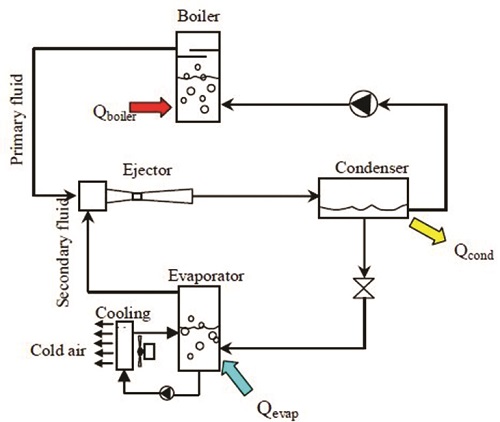
Figure 6: Schematic representation of steam jet refrigeration system
Vortex Tube Cooling
The vortex tube is device, which separates a high compressed flow into low pressure stream and high pressure stream of different energies. This results in a difference in temperatures. George Ranque, the French metallurgist and physicist, accidentally invented the first vortex tube in 1928. The documents and vortex tubes of another scientist Hilsch were found after the World War II. The vortex tubes are thus, generally referred to as Ranque-Hilsch vortex tube. The vortex tubes can be categorized into uni-flow vortex tube and counter-flow vortex tube. As the name implies, the warm and cold streams pass in the same direction in the uni-flow type. On the other hand, in the counter-flow vortex tube type the cold flow move in the opposite direction with respect to the hot stream. Generally, the counter flow is preferred over the uni-flow for its efficient energy separation. The compressed air is the working fluid in vortex tube cooling. Thus, it is environmentally harmless with zero global warming potential (GWP) and zero ozone depletion potential (ODP). The working of a vortex tube is shown in figure 7.

Figure 7: Working of a Vortex cooling tube
The compressed air injected into a swirl chamber exits as two streams namely hot stream and cold stream. The compressed air entering the swirl chamber is subjected to a high rate of rotation. The hot gas is allowed to escape via the conical nozzle. The remaining air returns through the centre of the vortex tube to exit as cold air. The pressure difference occurs through the gas due to the centrifugal force. Then compression at the walls, expansion at the centre, and heat transfer between the two streams within the vortex tube takes place resulting in the cold and hot air stream separation.
The vortex tubes are inexpensive and are used in nontoxic spot cooling. The availability of large amount of compressed air limits its use. There is initial energy cost of compressing the air involved in this type of cooling. Thus, a large amount of compressed air available as a waste or free energy source provides the scope for using this technology. In the absence of large amount compressed air, vortex tubes will only be suitable for spot cooling or where toxicity or flammability is a greater concern than energy.
Thermo Acoustic Refrigeration
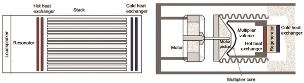
Thermo acoustics is the science which deals with sound and thermal energy. Byron Higgins observed thermo acoustic phenomenon. Hofler built a first thermo acoustic cooler at Los Alamos National laboratory. The thermo acoustic refrigeration systems use sound waves to produce cooling effect. The cooling effect is achieved through compressing and expansion of an inert gas such as helium, argon, air or a mixture of gases in a resonator. The thermo acoustic devices are mainly divided into standing wave systems and traveling wave systems and are shown in figures 8(a) and 8(b) respectively. The main components in standing wave systems are a closed cylinder, an acoustic driver, a porous media called stack, and two heat exchangers. In standing wave system, a loudspeaker produces sound waves which are used to create a resonant standing wave inside the stack. A temperature difference along the length of the stack is produced as gas oscillates within the stack, due to expansion and compression by the sound wave. On the other hand for traveling wave system, the driver is a motor and piston. The temperature difference for this system occurs in a regenerator rather than a stack unlike in stand wave system. The regenerator consists of a matrix of small channels. As the pressure is increased and decreased, the air will oscillate between the hot and cold heat exchangers through the regenerator matrix. When the pressure is high, the gas moves towards the hot heat exchanger and when the pressure is low, it moves towards the cold exchanger, thereby transferring heat. The acoustic refrigeration technology is most suitable for low capacity equipment. The main benefit of the technology is that it uses environmentally safe, inert gases such as air, argon, and helium. The inefficiency of systems which have been already built and tested is a result of inadequate tolerances in assembled apparatus. Also, the heat exchangers were found to be the cause for high cost and complexity.
 a) b)
a) b)
Figure 8: Representation of (a) Standing wave thermo acoustic refrigeration and (b) Travelling wave thermo acoustic refriration
Air Cycle Refrigeration
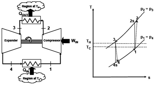
Air cycle refrigeration is based on the reversed Joule (or Brayton) cycle. The ideal cycle considered for air refrigeration cycle is called Bell-Coleman cycle. The schematic diagram for the arrangement of different components of Bell-Coleman cycle has been shown in figure 9(a). The ideal cycle (1-2s-3-4s-1) and also the cycle considering the irreversibilities in the compressor and expander (1-2-3-4-1) have been shown on the temperature-entropy (T-s) diagram in figure 9(b). Air cycles can be classified as closed, open or semi-open/closed. Closed cycles are sealed systems and consequently there is no direct contact between the working fluid and the product being cooled. Open cycles can be open on either the low-pressure side or the high-pressure side of the cycle. Cold air leaving the system passes through the refrigerated space coming in direct contact with the product being cooled. Since air is used as cooling medium, no cost of refrigerant is involved thus making the system quite cheap. Also, as the main compressor is employed for the compressed air source, there is no problem for extra space, extra fixation of the compressor. Also there is no additional vibration. The chilled air is directly used for cooling; the costs of separate evaporator and its weight are eliminated. As the air is refrigerant, minor leakage of the same is tolerated vis-à-vis that of the costly refrigerant. There are no complicated parts involved rendering low maintaining cost. It is light weight per ton of refrigeration compared to other refrigeration system and thus it is used in aircraft refrigeration. On the contrary to the benefits discussed the system shows low COP. Also, there is only sensible cooling and no evaporation of the refrigerant.
a) b)
Figure 9: (a) Air cycle refrigeration arrangement (b) Air cycle refrigeration on T-s diagram
Aircraft Refrigeration
The gas cycle or air cycle refrigeration is widely used for the air conditioning of different types of aircrafts. Although, the COP of this cycle is much less than that of vapour compression cycle, it is preferred for aircraft refrigeration system due to its less weight and other advantages. Normally, in an aircraft, a compressor is already present for the gas turbine power cycle. A part of the compressed air is used for air conditioning purpose as show in figure 10.

Figure 10: Simple aircraft air conditioning system
Of course, in an actual aircraft air conditioning, the above cycle is modified using the ram effect of high velocity air jet and more number of compressors and heat exchanger. The initial compression is done by using the ram effect of air entering into the high velocity aircraft. The scheme has been shown in figure 8 on the T-s diagram. Other improved systems used for aircraft refrigeration after the modification of the basic systems include Bootstrap system, Regenerative system and reduced ambient system.
Conclusion
The vapour compression refrigeration system has caused huge damage to the environment. The Montreal protocol has already banned the CFCs and the HFCs which gave high COP to the VCR system. Now, to face this challenge there are two ways. First one is to opt for new refrigerants with zero ODP and very low GWP. The other way is to adopt new refrigeration technologies like the ones discussed above. The magnetic refrigeration has already gained importance and put into practice. The aircraft refrigeration and air refrigeration systems use air as refrigerant, which is very easily available and are being used in aircrafts. Likewise, focus should be laid on the other existing methods as they are simple and does not use harmful refrigerants as in VCR systems. These alternatives technologies are not all new and were used earlier. But due to the domination of VCR system, they were put aside. Now, the time has come for crucial research to be carried on these technologies, so that they can replace VCR technology. The aim for research should be to develop new refrigerants and new technologies to the meet the cooling demand of the world without effecting our environment.

If you want to share thoughts or feedback then please leave a comment below.


Adopting New Refrigeration Technologies | Cooling India Monthly Business Magazine on the HVACR Business | Green HVAC industry | Heating, Ventilation, Air conditioning and Refrigeration News Magazine Updates, Articles, Publications on HVACR Business Industry | HVACR Business Magazine
acboiqjxlp
[url=http://www.g650w6697t1854kpopuvdrxu9j0z129qs.org/]ucboiqjxlp[/url]
cboiqjxlp http://www.g650w6697t1854kpopuvdrxu9j0z129qs.org/