


The renewable energy sector is rapidly evolving globally and among them, solar energy is acknowledged as the most effective form of renewable energy, especially in a country like India. The India solar power market size is estimated to grow at a CAGR of 34.24% between 2022 and 2027. The market size is forecast to increase by USD 273.82 billion.
In addition, the demand for semiconductors is growing quickly. This will result in enhancing India’s global position in the technology industry. The Indian Semiconductor Market Size is expected to reach USD 271.9 Billion By 2032, at a CAGR of 25.7% during the forecast period 2022 to 2032. The semiconductor business has grown to become one of the most essential industries, as it has become an inseparable part of practically all sectors.
Based on the above analysis, the demand for solar cells and semiconductors is increasing rapidly. These industries require clean rooms with controlled temperature as well as humidity as per their process demand. The air recirculation system in the cleanroom of the solar cell and semiconductor facility occupies about 10% of the total plant’s power consumption. Due to a huge volume of recirculation airflow rate, a proper design on the air path can reduce airflow resistance and therefore increase the energy efficiency significantly.
Traditional wall-return re-circulation air systems with ceiling-supply and wall-return air grilles are common in non-unidirectional airflow industrial cleanrooms as shown in Figure 3. It is traditionally used for ISO Class 6 through ISO Class 9 industrial cleanrooms, Class C and Class D pharmaceutical cleanrooms, and operation rooms in hospitals. Figure 3 illustrates a common arrangement of the airflow pathway in such cleanrooms, to which filtered Supply Air (SA) is introduced from the cleanroom ceiling through duct while Return Air (RA) is directed to vertical air grilles close to the cleanroom floor level. Such re-circulation systems normally have longer airflow circulation pathways, which inherently induced higher airflow resistance, resulting in higher fan power demand per unit of airflow rate delivered.

To overcome the airflow resistance, Fan Filter Units (FFUs) used in the traditional wall-returned re-circulation system are designed to operate with high external pressures as shown in Figure 4, which also induce high negative pressures in supply air plenums. The negative pressures within plenum can increase the risks of infiltration of outdoor air and contaminants. A longer airflow pathway corresponds to a higher level of negativity of the air pressure inside the supply air plenum, thus inducing higher risks of cross-contamination.
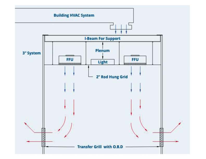
Dry Cooling Coil (DCC) system with FFUs & MAU
To overcome the above-mentioned drawbacks, a new re-circulation system using Dry Cooing Coil (DCC) is proposed. This new system exhibits shorter air re-circulation paths while providing effective environmental controls (e.g., non-viable particle of 0.3-μm and temperature control) for a cleanroom. In order to address the issues induced by traditional airflow circulation system, newly designed DCC system is introduced with FFUs to effectively remove the heat dissipated from process tools while maintaining the required cleanliness level for environmental control.

Figure 5 shows the filtered air passes through the FFUs from the plenum and return air is taken through the return air riser via DCC to the plenum itself. A Make-up Air Unit (MAU) supplies the required fresh air / outside air into the plenum while maintaining proper filtration level. The DCC effectively removes the heat dissipated from process tools.

Dry Cooling Coil (DCC)
Dry Cooling Coils (DCC) can contribute to energy efficiency in cooling systems. The DCC contains low temperature refrigerant or coolant and medium chilled water as cooling medium to extract heat from the air. They also enable precise temperature control and can be integrated into energy-efficient HVAC systems, optimizing overall energy performance. The main function of DCC is to remove high sensible load (heat generated by furnaces, lighting, machinery, etc.) without spending abundant amount of energy. Figure 6 shows the typical schematic diagram of dry cooling coil.
Conclusions and Recommendations
While introducing DCC system in cleanrooms, it consist shorter air re-circulation paths while providing effective environmental controls. Thus, energy efficiency increases of the overall system.


In addition, Solar Cell and Semiconductor industries are generating high sensible load due to their critical processes. To mitigate this huge sensible load demand in an energy-efficient way, DCC can be a paramount choice. The Dry Cooling Coil (DCC) concept is used to eliminate high sensible load especially when the SHF (Sensible Heat Factor) is coming nearly between 0.85 to 1.

Frank Gandhi has done B.Tech in Mechanical Engineering from Pandit Deendayal Energy University (Formerly PDPU), Gandhinagar. Currently, he is working at Avant Garde Cleanrooms & Engg. Solutions Pvt. Ltd. (ACES). He has provided technical solutions related to HVAC, Refrigeration and Cleanroom for various industry like Solar, Pharmaceutical, FMCG, Commercial, Industrial, Hospitality etc. He is also a prominent member of ISHRAE.


