
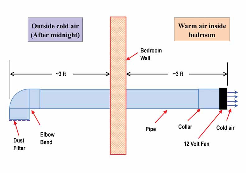
An article “Pipe Cooler for Poor People” was published in January 2025 issue of Cooling India. In figure 1 the design and mounting of pipe cooler is reproduced. In figure 2, photograph of fully assembled Pipe Cooler is reproduced. It consists of a long pipe that is partially extended outside and partially inside the house. At the outside end of the pipe, an elbow bend with dust filter is attached. At the inside end, a collar with a 12V fan is attached. After midnight, when outside air becomes cool, the fan is started. It provides cool air directly to the user sleeping on the bed. The long pipe avoids mixing of indoor warm air.

Advantages of Pipe Cooler
- It provides outside cool fresh air after midnight.
- Very low power consumption
- Very low cost
- Simple low-cost battery backup can be provided.
Limitations of Pipe Cooler
- Cool air is available only after midnight.
- In many cities, midnight air temperature is in the range of 25 to 30 °C. which is not very comfortable.
To overcome above limitations, pipe cooler needs improvement. The improved pipe cooler has to be useful throughout the night. Also, in cities where the midnight temperatures are above 24° C, it should provide satisfactory cooling. Therefore, there is a need to reduce the air temperature by few degrees. Which can be done by using Peltier modules.
Peltier Thermo-Electric Cooler Modules
The Peltier effect is a thermoelectric phenomenon where an electric current passed through a junction of two different conductors or semiconductors cause one junction to become hot (release heat) and the other to become cold (absorb heat).
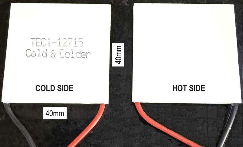
Thermo-Electric Cooler (TEC) modules are designed based on Peltier effect. It consists of large number of semiconductor junctions. All hot junctions are on one side and the cold junctions are on another side. Photograph of TEC module is shown in Fig. 3.
Selection of TEC Module
TEC modules are available in different current ratings. Based on the cooling power requirement, the module with appropriate current rating is chosen. However, performance depends upon the internal resistance of the module. In two ways this resistance affects the cooling performance. Higher the resistance, more heat is generated inside the module. Secondly, higher resistance limits the current through the module that reduces the cooling performance.
Hence, while selecting the modules, one can check the resistance at the terminals using a multi-meter. The value of this resistance should be close to the value given in the data sheet.
The module selected here is TEC1-12715 from Cold & Colder. It is rated at 15 Amp. The maximum voltage we can apply is 15V. In this proposed design, the current is limited to about 6 Amp. Here, we are cascading two modules. And total number of modules used is 4. One pair of modules will give few degrees of cooling. With two modules cascaded, we will get double cooling. As the worst-case night air temperature will be around 30°C. We need to bring it down by 6°C. Which means, each pair should cool the air by 3°C.
The heat from the HOT side is removed using water cooling.
Construction of Improved Pipe Cooler
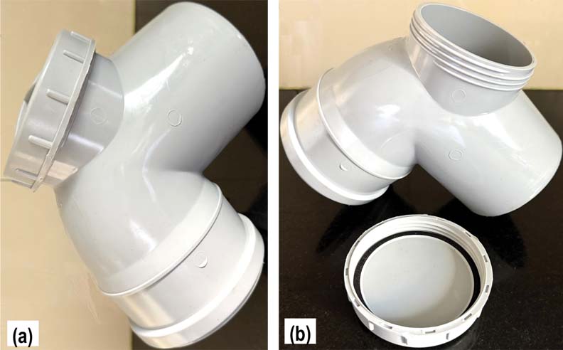
In order to incorporate TEC modules, the elbow bend attached at the outside end of the pipe is replaced with another elbow bend having a “door” as shown in Fig. 4. The door has a cap. The TEC modules are mounted on this cap.
Material Required
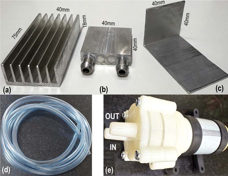
See Figures 5 and 6.
- Peltier Modules type TEC1-12715 (4 pcs)
- Elbow bend with door (1 pc)
- Heat sink 75mm X 40mm X 18mm (4 pcs)
- Aluminium cooling blocks 40mm X 40mm (2 pcs)
- Aluminium 1mm thick L plate with one side 40mm X 40mm (2 pcs)
- Plastic tube 10 mm diameter
- 12VDC pump (NOT submersible type) (1 pc)
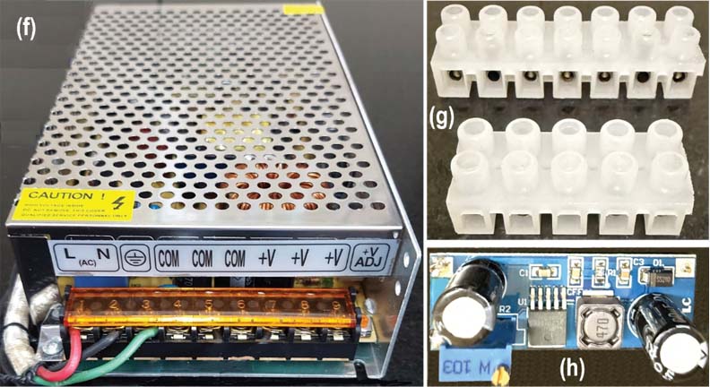
- AC to DC power supply 36V 10A (1 pc)
- Screw type terminal strips (2 pcs)
- Buck converter type XL7015 (2 pcs)
- About 100 L water container with cover.
Pump Selection
A small pump operating on 12VDC power supply is selected for water circulation in the cooling blocks. A non-submersible type pump is chosen. Power supplied to the pump finally gets converted in to heat. If we use a submersible type pump, then, the heat generated will be transferred to the cooling water and its temperature will increase. Hence to avoid unnecessary heating of water, the pump is mounted on the cover of water container.
Peltier Assembly
The Peltier assembly is mounted on the cover of elbow piece. Advantage of this approach is, the design becomes modular. Peltier assembly can be removed very easily by just taking out the cover. It can be easily mounted on another pipe cooler etc. Repairs also become easy. No need to handle the long pipe.
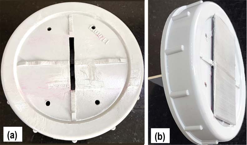
Figure 7 (a) shows the cover in which a 40mm long, 2mm wide slot is made at the centre. Also, four 3mm holes are drilled. Fig 7 (b) shows the two L shaped pieces inserted in the slot. The 40mm X 40mm sides of L pieces are on the top of the cover.
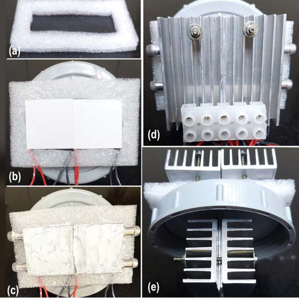
Figure 8 shows the Peltier assembly. Fig. 8 (a) shows a 10 mm thick PUF piece of size 110mm X 80mm. A slot of size 80mm X 40mm is made in this PUF piece. This piece is placed on the cover assembly. Two TEC modules are kept on the surface of one L piece, one above the other. Another pair is placed on the other L piece on top of the cover. Ensure that the cool sides are in contact with L piece. The top visible sides of TEC modules in Fig. 8 (b) are the Hot sides. On these Hot sides, two Aluminium water cooling blocks are kept as shown in Fig. 8 (c). Two heatsinks are mounted on these cooling blocks. The whole assembly is fastened with four screws as shown in Fig. 8 (d). Apply thin layer of heat conducting paste to surfaces of L pieces, TEC modules, cooling blocks and the heat sinks. Two more heat sinks are mounted on the inner legs of L pieces as shown in Fig. 8 (e).
Power Supply Design
Following voltages are needed for powering the improved pipe cooler system.
- 36V for TEC modules
- 12V adjustable power supply for water pump
- 12V adjustable power supply for cooling fan
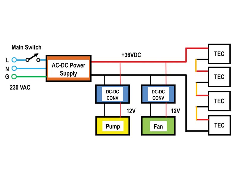
To generate the above voltages, a 36V 10 Amp SMPS is selected as shown in the block diagram of Fig. 9. The 36V output voltage is directly connected to the 4 TEC modules which are connected in series. The TEC module internal resistance and the wiring resistance adds up to about 6 ohms. When TEC modules are connected to 36V, about 6 Amps of current flows.
To generate two 12V variable power supplies, two buck converters are used. These are DC to DC converters type XL7015. These can handle up to 80V input voltage. The 36 V power is also connected to the input terminals of the converters as shown in the block diagram. The maximum output voltage is 20V, which is adjustable using the trim potentiometer provided. We have to ensure that the converter output voltage never exceeds 12V. Converter maximum output current is 800 mA. Here, our requirement is less than 200 mA. Hence the selected converters are a suitable low-cost option. Note that we have to use thick wire for TEC module connections. For fan and pump, the current is in milli amps, hence standard general purpose wire will be ok.
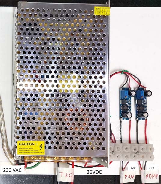
Figure 10 shows the main 36V SMPS unit. Supply to the TEC module assembly is directly given from this power supply. Two buck converters are mounted near the main power supply. The input to these converters is 36V derived from the main power supply. The output from these converters is brought to the connector terminals. From this connector the Fan and the Pump get their power.
Integration
The cooling pipe is brought out from window of the room. Elbow bend is attached to the cooling pipe external end. The Peltier assembly is fixed to the elbow door. The fan with collar is inserted at the inside end of the pipe.
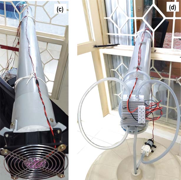
The plastic container stores about 100 litres of cooling water. The pump is mounted on the cover as shown in Fig. 11 (b). Two holes are made at the centre of the cover for inlet and outlet tubes. One of the tube goes to the IN port of the pump. The OUT port of the pump is connected to the Peltier assembly. Water coming from Peltier assembly after circulation, goes back to the container. CAUTION: Do not use open buckets etc for storing water. As it will breed mosquitos. Also, the dust will choke the pump over a period of time. The fully integrated system is shown in Fig. 11. The power supply unit is kept inside the room. Wires are brought to power the TEC modules and the pump. Connection to the fan is made inside the room itself.
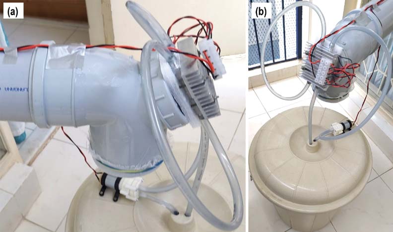
with pump mounted on the cover…
Figure 12 (c) shows the pipe as seen from inside the room. Fig. 12 (d) shows the pipe as seen from outside. The Peltier assembly and the Pump needs to be protected from dust and rain. Simple plastic covers can be used. This is not shown in the figures.
Testing
When the user turns ON the power to the unit, fan turns ON. It sucks outside air through the pipe. The air flows over the two heats sinks which are mounted on the L pieces inside the cover. The TEC modules cool these heat sinks. Therefore, the air passing over these heat sinks also gets cooled. Water circulating through the cooling blocks continuously remove the heat from the HOT sides of the TEC modules. Thus, keeping the temperature on the HOT side as low as possible. As the volume of water is large, it takes long time to heat up. As the water container is outside, the cold air removes the heat from the container and keeps the water cooler. CAUTION: Do not start the system without turning ON the pump. If cooling water is not circulated, then the TEC module temperature will rise and will get burnt.
Test was carried out to see how much cooling is possible by using only two TEC modules. About 3°C reduction in the air temperature was measured. Then two more TEC modules were cascaded. With four TEC modules, 6°C cooling was obtained. This is what is required for pipe cooler, because in the night the outside temperature will be around 30°C. Note that the temperature reduction is highly dependent on the air speed. If air speed is too high then we may not get 6°C reduction. If air speed is too low, then the temperature reduction will be more than 6°C. If cooling is insufficient, then, we can increase the voltage supplied to the TEC modules. In that case, we have to increase the current rating of the power supply also.
Suggestions
- Aluminium L pieces could be replaced by a single U-shaped copper piece. In that case two slots (1 mm width) have to be made 80mm apart on the door cover. Then insert the U-shaped copper piece. The temperature drop in the copper piece will be less than that of Aluminium L pieces.
- The performance of the Pelter assembly can be optimized by testing the system at various TEC module supply voltages to get optimal performance. Also, the water circulation rate will have effect on the performance.
Costing and Power Savings
The approximate cost of prototype system is about Rs 6000. With higher production volumes the cost can come down by about 30%. It consumes about 250W of power. If the unit runs for 8 hours, the energy consumed is about 2 kWh or 2 Units. Thus, monthly running cost will be about Rs 500 in terms of electricity bill. This, if compared with a standard AC unit, is only about 20%. Therefore, the proposed improved pipe cooler will save about 80% energy consumption in comparison with a standard AC. With 250W power consumption, the unit can be connected to a home inverter for power backup.

Vijay Deshpande has done PhD from IIT Kanpur in Electrical Engineering. He has worked in several companies in India. He worked as Technology Specialist and retired from Honeywell India. His current interests include working on cost effective Cooling Techniques and also on Solar Photovoltaic Systems. He has published several research papers in International Journals and published many articles in leading magazines.