


Professional Refrigerators, Freezers, Cold Water Dispensers and Chillers consume significant amount of energy. Also, any degradation in their performance may result into spoilage of food items kept inside. The vendor thus suffers huge losses if the performance of the cooling equipment is not satisfactory.
One of the reasons for reduced performance of these units is that, they are always surrounded by stagnant warm air. The reasons for this are:
- The equipment manufacturers recommend at least 5 cm clearance on all sides of the equipment. However, due to space constraints this gap is not maintained. Which blocks the movement of air.
- The units kept in corner places, where there is no free movement of air. Hence, the whole area itself is warmer.
- Many times, some material is stuffed in these gaps which further stops free movement of air.
To overcome this problem forced air circulation on the outside surface of the cooling equipment is proposed here. For this, sleek Instrument Cooling BLDC Fans are attached to the external surface of the cooling equipment using small magnets. With the use of magnets, it is easily possible to attach and remove these fans. Also, it is easy to change its location on the equipment surface. Further, as there are no changes made to the cooling equipment, the warranty of the equipment remains valid.
Another concern vendors may have is the power consumed by these fans. Which may increase their electricity bill. Therefore, to overcome this issue, Solar powered cooling fans are proposed here. However solar only system will work in the day time. During night and when there are heavy clouds the fans may not work. This problem is solved by using mains power backup. In the design stage, care has been taken such that, minimum power is consumed from the mains power supply.
Block diagram
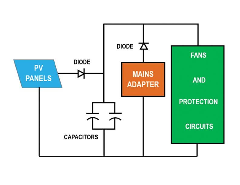
Figure 1 shows the block diagram of the Solar Powered Fans. Solar Photo Voltaic (PV) Panels are connected to the fans through a diode. Electrolytic capacitors are connected to the solar output after the diode. The capacitors are used to filter out short duration fluctuations in the PV panel voltage during cloudy skies. The diode prevents discharging of capacitors if the PV voltage suddenly drops. A mains adapter is also connected to the fans through another diode. This diode prevents solar power entering into the adapter circuit.
Fans and PV panel selection
Instrument cooling BLDC fans rated at 12 VDC are very commonly available in the market at reasonable price. Hence, these fans are selected. The specifications of these fans are as follows:
1.Rated Voltage: 12 VDC
2.Current Consumption: 0.25 Amps
3.Size: 120mm X 120mm X25mm
Standard 10 Watt PV panels are easily available in the market. The specifications of these panels are as follows:
1.Power Output:10 Watt Peak
2.Voltage at maximum power Vmp: 17.5 Volts
3.Current at maximum power Imp: 0.57 Amps
4.Size: 13 in X 12 in X 1 in
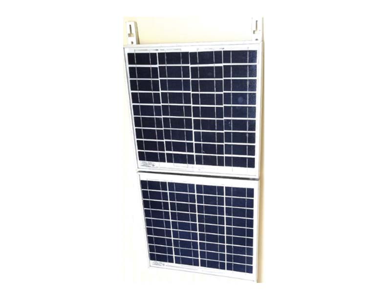
From the above specifications it is observed that, the fan rated voltage is 12 V and the PV output voltage is 17.5 V. Hence there is a mismatch in their voltages. To overcome this problem, we will use two PV panels and connect them in series. Fig. 2 shows two 10 W panels fixed on a single frame and connected in series. Then the PV panel output voltage becomes 35 Volts. Now if three fans are connected in series, the fan voltage rating becomes 36 V. Thus, the voltage generated by two PV panels matches with the three fans connected in series without needing any converter circuit.
The circuit diagram of solar powered fans is shown in Fig. 3. Two PV panels, Panel1 and Panel2 are connected in series. The output of these panels Vpv is connected to the fans through Schottky diode D5 (1N5819). Two electrolytic capacitors C1 and C2 (4700uF 50V) are connected to the solar panel output Vpv. These capacitors will filter out small sudden variations in Vpv due to clouds. The diode D5 prevents discharge of capacitors into the PV panel if the Vpv goes below capacitor voltage.
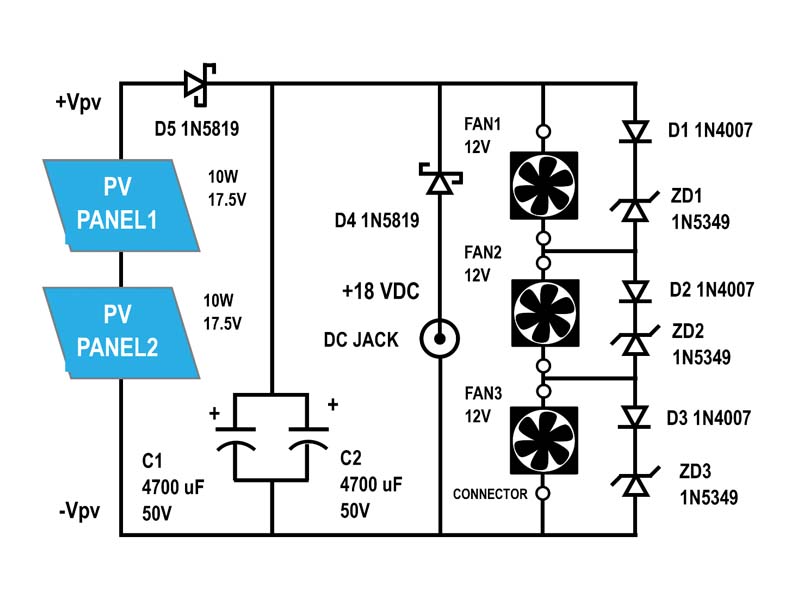
Three fans FAN1, FAN2 and FAN3 are connected in series and connected to Vpv. The adapter supplies 18V DC to the fans through the DC Jack and diode D4 (1N5819) in series. During the day time, the panel voltage Vpv is about 35 V, hence, the diode D4 is reverse biased and no current is drawn from the adapter. In the evening when Vpv falls below 18 V, then diode D4 gets forward biased and supplies power to the fans. The BLDC fans usually work down to 6 Volts with reduced speed. During night time, lower speed is sufficient as the ambient temperature is lower than in the day time. With 18 volts the power consumed by the adapter is less as given below:
Power Consumed by Adapter (during night) = 18 V x 0.125 A = 2.25 W
Energy consumed by the adapter in the night = 2.25 X 12 = 27 Watt Hours
Energy consumed in one month = 27 x 30 = 810 Watt Hours
Hence approximately 1 unit of power is consumed by the adapter. So, it will add just 5 rupees to the monthly bill.
FAN protection circuit and fan segregation
The fans available in the market are for general purpose applications. Hence, usually have about ±10 % tolerance. When used as a single fan, or used in parallel, this tolerance does not matter. However, when used in series, the voltage distribution is not uniform due to differences in their current consumption.
When these fans are connected in series, same magnitude of current flows through all the fans. Now, if we measure the voltage across each fan, we will see that these voltages are slightly different, but the sum of three voltages equals the applied voltage. For example, we may see following voltages:
Vfan1 = 11 V; Vfan2 = 13 V; Vfan3 = 12 V; SUM is 36 V = applied voltage
The reason for this unequal voltage distribution is the differing impedances of each fan due to the manufacturing tolerances. Whichever fan has lower impedance (relative to other fans), will show less voltage. The fan having higher impedance will show higher voltage.
From the above example it is observed that the fan with 13 V, exceeds the rated voltage of 12 V and is likely to get damaged.
There are two solutions for this problem.
- FAN grouping: During production we have good stock of fans. Then, we can apply 12 V to each of the fans and measure the current. Make groups of fans drawing same value of current. Then, for one system use all three fans from the same group.
- Fan Protection Circuit: The individual fan protection circuit is shown in the circuit diagram. FAN1 has connected in parallel, one diode D1 (1N4007) and one 12 V Zener Diode DZ1 (1N5349). Similarly for other fans. The Zener diode clamps the voltage across the fan to 12 V. Ideally only Zener diode is sufficient. However, it is observed that the 12 V Zener starts clamping at 11.3 Volts itself and fan never gets 12 V. Diode D1 adds another 0.7 V and thus we get exact 12 V clamping for fan voltage.
The user can decide which protection approach is suitable. However, it is recommended that by incorporating both approaches, the reliability of the system will be better.
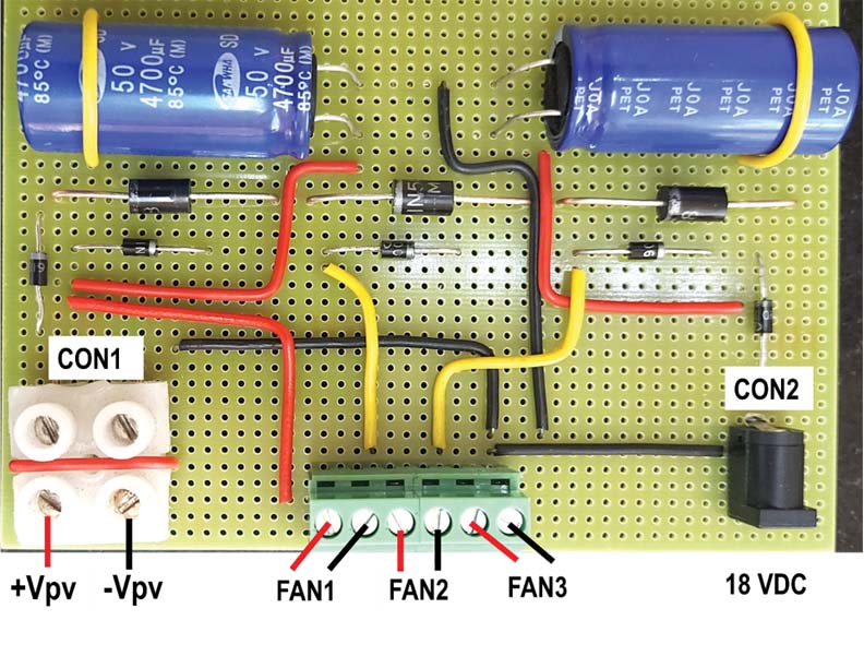
- PCB Assembly: Fig. 4 shows the fan controller PCB layout and assembly. To the connector CON1 +Vpv and -Vpv cables are connected. CON2 is a DC jack provided for inserting the 18 V Adapter pin. The terminal block has 6 terminals to which 3 fans are connected. Other components eg. Diodes and capacitors are connected as shown in the figure.
Fan assembly
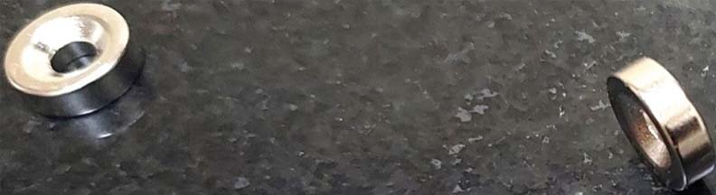
Low noise cooling fans are selected. A larger fan of size 120 mm x 120 mm is selected. Larger size fans will produce less noise. Also, cooling area will be bigger. Figure 5 shows the complete system with interconnections. Front view of Fan1 and Fan3 is shown. Two ring magnets (12 mm dia x 4 mm thk) are fixed at two diagonal mounting holes of the fan using M3 x 40 mm screws. A closeup view of the magnets is shown in the Fig. 6. The screws are passed through the hole of the magnet and fixed as shown in the figure. Magnets produce a gap of 4 mm between fridge surface and the fan blades. If more gap is required for smoother flow of air, then extra nylon washers could be added between magnet and fan housing. This assembly can be magnetically attached at any desired location on the fridge side walls. Do not drag the fan on the fridge surface as it may scratch the paint.
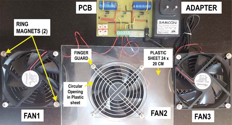
In Fig. 5, FAN2, back side view is shown. A stiff plastic sheet of about 240 mm x 200 mm is fixed as shown. A circular opening of same size as the fan blade diameter is cut in the plastic sheet, for air to flow. A finger guard is then placed and nuts are tightened for each fan. The plastic sheet redirects the air from the fan on to the fridge surface, thus increasing effective cooling area. Note that only one fan is shown having plastic sheet. Sheets to should be attached to all the fans.
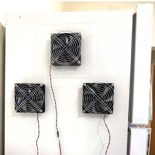
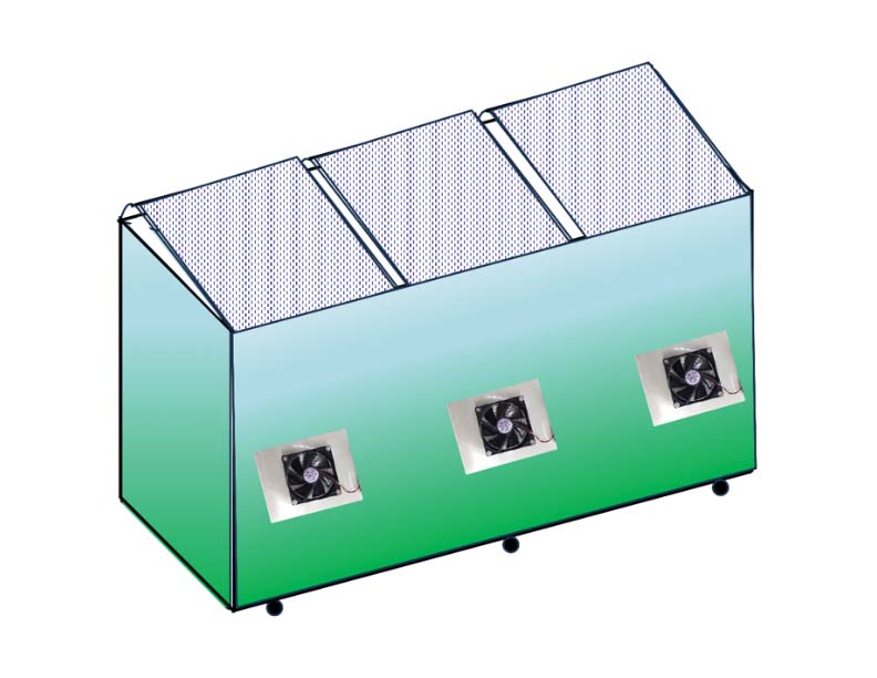
- Fan Mounting: Figure 7 shows the mounting of fans on the refrigerator or any other chiller surface. User can identify hot spots where there is maximum heat. In those locations the fans should be mounted for best results. Fig. 8 shows three fans three fans mounted on a chest freezer rear side.
Tips for further improvement:
- Instead of fan with plastic housing, select fan with aluminium housing. This aluminium housing will absorb heat from the freezer walls, which will be removed by the circulating air.
- For large capacity chillers, two such systems are recommended.
Conclusions
Solar cooling fans are proposed for external air circulation in commercial freezers, cooler and chillers. The cost of the proposed system will be around 1000 rupees when mass produced. In the day time it will run on solar power and during night it runs on mains power.
To minimize main’s power consumption, only half the rated voltage is applied to the fans. This is acceptable because in the night the ambient temperature is less.
This system will provide improved performance of the cooler units because it moves away the stagnant hot air. Moreover, by slightly reducing the load on the compressor, the maintenance and down times will be reduced; and also bring a small savings in the electricity bill. Thus, the system offers multiple benefits.

Vijay Deshpande has done PhD from IIT Kanpur in Electrical Engineering. He has worked in several companies in India. He worked as Technology Specialist and retired from Honeywell India. His current interests include working on cost effective Cooling Techniques and also on Solar Photovoltaic Systems. He has published several research papers in International Journals and published many articles in leading magazines.