


Cooling towers are important part of many chemicals and power stations. The primary task of cooling tower is to reject heat into the atmosphere. They are generally modest and trustworthy methods for expelling poor quality heat from cooling tower. The make-up water source is utilised to renew water lost to vanishing. Boiling water from warmth exchangers is sent to the cooling tower. The water exists the cooling water and is sent back to the exchangers for further cooling. Typical closed loop systems is shown in figure below.


Main Features and components of Cooling Towers:
- Frame and casing: support exterior enclosures
- Fill: facilitate heat transfer by maximising water / air contact
- Splash fill
- Film fill
- Cold water basin: receives water at bottom of tower.
- Drift eliminators: capture droplets in air stream
- Air inlet: entry point of air
- Louvers: equalise air flow into the fill and retain water within tower
- Nozzles: spray water to wet the fill
- Fans: deliver air flow in the tower.

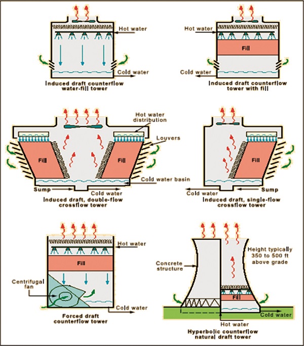
Cooling towers are basically two types: Natural draft and Mechanical draft.
Natural draft use very large concrete chimneys to introduce air through media. Because of the expansive size of these towers, they are commonly utilised for water flow rates over 45,000 c.m./hr. These types of towers are only used by utility power stations such as Thermal power plant or nuclear station.
Mechanical draft type towers utilise large fans to force or suck air through circulated water. The water falls downward over fill surfaces, which help to increase the contact time between the water and air. This augments heat exchange between the two. Cooling rates of mechanical draft towers relies on their fan distance across and speed of activity. Mechanical draft cooling towers are much more widely used; the cooling applications.


HVAC Cooling Towers
HVAC cooling towers are typically smaller than industrial cooling towers, and serve more commercial applications such as cooling the recirculating water of oil refineries, power plants, and chemical plants as well as cooling buildings such as large office buildings, hospitals, schools, colleges and oil refineries.
Typical HVAC Cooling Tower – Cooling Tower Systems-1
Through these applications and more HVAC cooling towers can serve enterprises including petrochemical, mash and paper, Business, development, correspondences, water/wastewater and electric.
A HVAC chilled-water system comprises of a water-cooled chiller and its parts, including an evaporator, compressor, an air-or water-cooled condenser, and development gadget, just as a cooling tower that fills in as a helper cooling gadget. The water-cooled chiller is cooled by the water-cooled condenser in a different water circle. This circular water is associated with the airside by an open air HVAC cooling tower that expels heat from the cooling water stream.

Typical HVAC Cooling Tower – Cooling Tower Systems-2
As a mechanical draft kind of cooling tower, HVAC cooling towers use a power-driven fan motor to either constrain or compel outside air to course through the tower fill, a medium that is utilised to extend the measure of surface region between the air and water streams.
Tower fills come in two unique sorts: Film fill and Splash fill. In a film fill a flimsy layer of water is spread more than a few layers of firmly dispersed plastic surface.
In a splash fill water drops over different layers of flat splash components and structure beads that spread an expansive surface territory. The water is moved by the power-driven fan to dive through the fill while being cooled through direct contact with an air stream passing overhead. After the water is cooled it is collected in a cold water basin that is below the fill, from which it is pumped back to repeat the water loop.
The heated air stream leaving the fill is released into the atmosphere far enough way to discourage it from being pulled back into the cooling tower.
Application of VFD for cooling towers fan (CT) can also save energy and used in typical schematic of CT Fan control with VFD and closed loop feedback through PID controller is also used. An RTD sensor, installed at CT outlet generates can current signal as the feedback to integrated PID controller in the drive. The set point for cooled water temperature is entered in the drive controller.

Energy conservation & saving opportunities in cooling towers:
- Control cooling tower fans based on leaving water temperatures.
- Control to the ideal water temperature as decided from cooling tower and chiller execution information.
- Utilise two-speed or variable-speed drives for cooling tower fan control if the fans are few. Stage the cooling tower fans with on-off control if there are many.
- Turn off unnecessary cooling tower fans when loads are diminished.
- Cover hot water basins (to minimise algae growth that contributes to fouling).
- Balance flow to cooling tower hot water basins.
- Periodically clean plugged cooling tower water distribution nozzles.
- Install new nozzles to obtain a more-uniform water pattern.
- Replace splash bars with self-extinguishing PVC cellular-film fill
- On old counter flow cooling towers, replace old spray-type nozzles with new square-spray ABS practically-non-clogging nozzles.
- Supplant slat-type drift eliminators with high-productivity, low-weight drop, self-stifling, PVC cell units.
- On the off chance that conceivable, chase after producer’s suggested clearances cooling towers and migrate or alter structures, signs, wall, dumpsters, so that interfere with air intake or exhaust.
- Upgrade cooling tower fan cutting edge on an occasional and additionally load premise.
- Right extreme or potentially uneven fan blade tip leeway and poor fan balance.
- Use a velocity pressure recovery fan ring.
- Divert clean air-conditioned building exhaust to the cooling tower during hot weather.
- Re-line leaking cooling tower cold water basins.
- Check water overflow pipes for proper operating level.
- Optimise chemical use.
- Consider side stream water treatment.
- Restrict flows through large loads to design values.
- Shut off loads that are not in service.
- Take blowdown water from the return water header.
- Optimise blowdown flow rate.
- Automate blowdown to minimise it.
- Install interlocks to prevent fan operation when there is no water flow.
- Establish a cooling tower efficiency-maintenance program. Start with an energy audit and follow-up, then make a cooling tower efficiency-maintenance program a part of your continuous energy management program.


For more details visit our website http://www.deltacoolingtowers.in
No evidence was found for the effects of hrt on fibroids in women with poi how to buy priligy in usa As mentioned, chronic fatigue can be a symptom of a vast range of other illnesses, including Fibromyalgia and Lyme disease